 Learn About Structures
The method of sections is an alternative to the method of joints for finding the internal axial forces in truss members. It works by cutting through the whole truss at a single section and using global equilibrium (3 equations in 2D) to solve for the unknown axial forces in the members that cross the cut section. Since there are only three global equilibrium equations, we can only solve for three unknown member axial forces at a time using the method of sections. This process is similar to cutting a beam at a section to find the internal forces at that section.
The primary benefit of the method of sections is that, for a determinate truss, you can find the force in any individual member quickly without having to solve through the entire truss one joint at a time (which you must do when using the method of joints).
To perform a 2D determinate truss analysis using the method of sections, follow these steps:
- Check that the truss is determinate and stable using the methods from Chapter 2.
- Calculate the support reactions for the truss using equilibrium methods as discussed in Section 3.4.
- Select an appropriate section that cuts through the member that you want to find the axial force for. The section must cut completely through the truss and should cut through no more than three members. In special circumstances, four member cuts may be made (as will be shown in the example).
- Choose one of the cut pieces, the cut structure on the one side of the cut or the other (preferably the one with the least number of external loads).
- Use a free body diagram (FBD) of the cut piece to solve for the unknown internal axial forces in the members that cross the cut.
Example - Method of Sections
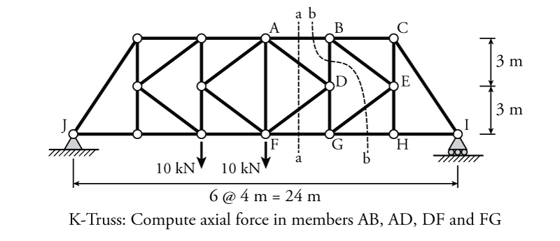
The truss shown in Figure 3.9 has external forces and boundary conditions provided. We must find the internal axial forces in the specific truss members AB, AD, DF and FG.
- Check determinacy and stability
This is a simple truss that is simply supported (with pin at one end and a roller at the other). From Section 2.5:
\begin{align*} m+r &= 2j \text{ for determinacy} \\ m+r &= 29 + 3 = 32 \\ 2j &= 2(16) = 32 \end{align*}Therefore, the truss is determinate. There is also no internal instability, and therefore the truss is stable.
- Find the support reactions using global equilibrium
Start with the moment equilibrium around point J:
\begin{align*} \curvearrowleft \sum M_J &= 0 \\ -10\mathrm{\,kN} (8\mathrm{\,m}) - 10\mathrm{\,kN} (12\mathrm{\,m}) + I_y(24\mathrm{\,m}) &= 0 \end{align*} \begin{equation*} \boxed{I_y = 8.33\mathrm{\,kN} \uparrow} \end{equation*}Vertical equilibrium:
\begin{align*} \uparrow \sum F_y &= 0 \\ J_y - 10\mathrm{\,kN} - 10\mathrm{\,kN} + 8.33\mathrm{\,kN} &= 0 \end{align*} \begin{equation*} \boxed{J_y = 11.67\mathrm{\,kN} \uparrow} \end{equation*}Horizontal equilibrium:
\begin{align*} \rightarrow \sum F_x &= 0 \\ J_x &= 0 \end{align*} \begin{equation*} \boxed{J_x = 0\mathrm{\,kN}} \end{equation*} - Select a section cut
The obvious choice for a cut is section a-a as shown in Figure 3.9, because it cuts through all of the members that we are trying to find axial forces for; however, the problem is that this section has four members, which we cannot calculate directly using only our three equilibrium equations. So, we need a way to cut down the number of unknown forces at section a-a from four to three.
To do this, we need to find a way to cut the truss such that we include one of the unknown forces from a-a, but which is also cut in a way that we can directly solve for that unknown force. For this problem, one way to do this is by cutting at section b-b as shown in Figure 3.9. This section shares member AB with the other section a-a. But, this section (b-b) still cuts through four members, meaning that we can't solve for all of the internal axial forces in those cut members either. So, how does this help us?
We cut section b-b in such a way that, even though we cannot solve for all four of the member forces across the cut, we can still solve for one of them (AB) by using the moment equilibrium equation. This is because the other three members at that cut (BD, EG, and GH) are all coincident through point G. This means that if we take a moment equilibrium around point G, then none of these member forces will contribute to the equilibrium, leaving only the force in AB, which can then be found easily. Once we know the force in member AB, we are left with only three unknown forces across the section cut a-a, which we can solve using only equilibrium. So, we will start with section b-b to find $F_{AB}$ which we will then use in section a-a to find the forces in the other three members.
- Choose one of the cut pieces
For section cut b-b, we will look at the piece of the structure to the right of cut b-b as shown in Figure 3.10. It makes sense to choose this side because it does not have any external forces and it has only one reaction component $I_y$. This will make the equilibrium equations less complicated. The solution will work the same if you choose the other side of the cut, but it will just be more work. When we go back to section cut a-a, we will look at the section to the right of the cut as well for the same reason.
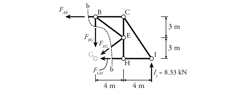 Figure 3.10: Method of Sections Example - Free Body Diagram for Cut Section to the Right of b-b
 - Use a free body diagram to solve for the unknown internal axial forces
For a simpler problem, only one cut would be needed if the section had only three members crossing the cut. For this problem, as previously described, we need to make two cuts and solve the equilibrium equations twice: once to find the force in member AB using section b-b and again to find the rest of the forces in the other members that cross section a-a.
The free body diagram for the cut section to the right of section b-b is shown in Figure 3.10. All of the unknown member forces across the cut are shown, and are assumed to be in tension (pulling away from the member). Although joint G is not within the cut section, it is left in the drawing as a reference point for the moment equilibrium. As mentioned previously, the point of this cut is only to find the force in member AB ($F_{AB}$). This section was chosen deliberately because the other three forces ($F_{BG}$, $F_{EG}$, and $F_{GH}$) all point direction through point G. So, if we evaluate the moment equilibrium about point G, we can solve directly for $F_{AB}$:
\begin{align*} \curvearrowleft \sum M_G &= 0 \\ F_{AB}(6\mathrm{\,m}) + 8.33\mathrm{\,kN} (8\mathrm{\,m}) &= 0 \\ F_{AB} = -11.11\mathrm{\,kN} \end{align*}which is negative, meaning that the member is actually in compression.
\begin{equation*} \boxed{F_{AB} = 11.11\mathrm{\,kN} \rightarrow \text{ (C)}} \end{equation*}Note that the right arrow ($\rightarrow$) here is relative to the cut member end. If we looked at the equilibrium around point B, the force $F_{AB}$ would still push towards the joint (to the right). But, if we were looking at the equilibrium around joint A, the force $F_{AB}$ would push in the other direction (to the left). Therefore, for truss members, it is often more convenient to think of the forces in terms of tension or compression instead of in terms of a specific direction. Tension forces always pull away from joints and members, compression forces always push towards joints and members.
Now that we know the value and direction of the internal axial force in member AB, we can go back to the primary cut section a-a and use equilibrium to find the rest of the forces. The free body diagram for the cut section to the right of section b-b is shown in Figure 3.11.
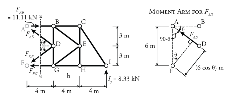 Figure 3.11: Method of Sections Example - Free Body Diagram for Cut Section to the Right of a-a
As before, even though points A and F are not within the section cut, they are left in the diagram as reference points. The angle $\theta$ may be found using trigonometry:
\begin{equation*} \theta = \tan^{-1} \frac{3}{4} = {36.9^\circ} \end{equation*}Since we $F_{DF}$ and $F_{FG}$ both point directly through point F, we can use a moment equilibrium around point F to find the third unknown force $F_{AD}$:
\begin{align*} \curvearrowleft \sum M_F &= 0 \\ -11.11\mathrm{\,kN}(6\mathrm{\,m}) + F_{AD}(6\mathrm{\,m})( \cos {36.9^\circ}) + 8.33\mathrm{\,kN} (12\mathrm{\,m}) &= 0 \\ F_{AD} = -6.94\mathrm{\,kN} \end{align*} \begin{equation*} \boxed{F_{AD} = 6.94\mathrm{\,kN} \searrow \text{ (C)}} \end{equation*}The moment arm for $F_{AD}$ in the moment equilibrium above was found using the geometry shown on the right side of Figure 3.11. The moment arm, as described previously in Section 1.2, is the perpendicular distance of force from the centre of rotation (in this case point F). For this problem, the moment arm for $F_{AD}$ is equal to $(6\mathrm{\,m})(\cos \theta)$.
The remaining unknowns may be found using vertical and horizontal equilibrium:
\begin{align*} \uparrow \sum F_y &= 0 \\ (-6.94\mathrm{\,kN}) \sin {36.9^\circ} - F_{DF} \sin {36.9^\circ} + 8.33\mathrm{\,kN} &= 0 \end{align*} \begin{equation*} \boxed{F_{DF} = 6.94\mathrm{\,kN} \swarrow \text{ (T)}} \end{equation*}Horizontal equilibrium:
\begin{align*} \rightarrow \sum F_x &= 0 \\ -(-6.94\mathrm{\,kN}) \cos {36.9^\circ} - (6.94\mathrm{\,kN}) \cos {36.9^\circ} + 11.11\mathrm{\,kN} - F_{FG} &= 0 \end{align*} \begin{equation*} \boxed{F_{FG} = 11.11\mathrm{\,kN} \leftarrow \text{ (T)}} \end{equation*}