 Learn About Structures
Virtual work is perhaps the most useful and widely applicable of the methods for calculating deflections that are described in this chapter. Unlike the moment area method and the conjugate beam method, it can be used to find the deflections of trusses, beams or frames (or, in fact, any mechanical system).
Work
The work in virtual work clearly implies energy, since work is one form of energy. Work is energy that is required to move mass around in space. You may recall that the expression for work ($W$) is equal to:
\begin{equation} \boxed{W = P\Delta} \label{eq:work} \tag{1} \end{equation}
where $P$ is a force on a body or structure and $\Delta$ is the displacement of that body or structure. This results in units of force times distance like $\mathrm{kNm}$. Work can also be expressed in terms of energy units where $1000\mathrm{\,J} = 1\mathrm{\,kNm}$. Likewise, in a rotational sense, work can also be defined as a moment multiplied by a rotation:
\begin{equation} \boxed{W = M \theta} \tag{2} \end{equation}
where $M$ is a moment acting on a body or structure and $\theta$ is the rotation of that body or structure. This type of work has the same units since it equals a moment (in $\mathrm{kNm}$ for example) multiplied by a rotation (in $\mathrm{rad}$ example). Radians are not really a unit of measurement in the conventional sense (nor are degrees). So, since rotation is effectively unit-less, the unit for work resulting from a moment is also in terms of a force times distance.
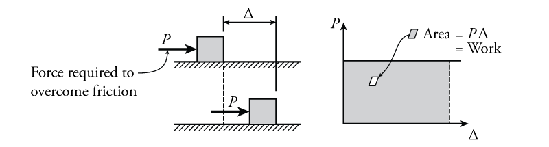
A classical example of work being done on an object is shown in Figure 5.14. In this figure, a constant force $P$ is applied to a body (the square box), causing it to slide to the right. The force is just enough to overcome the surface friction between the body and the ground. As the body is pushed, it displaces to the right by some amount $\Delta$. The work done by the force on the body is equal to the product of $P$ and $\Delta$ as previously shown in equation \eqref{eq:work}. This is also equal to the area underneath the force versus displacement plot as shown on the right side of the figure.
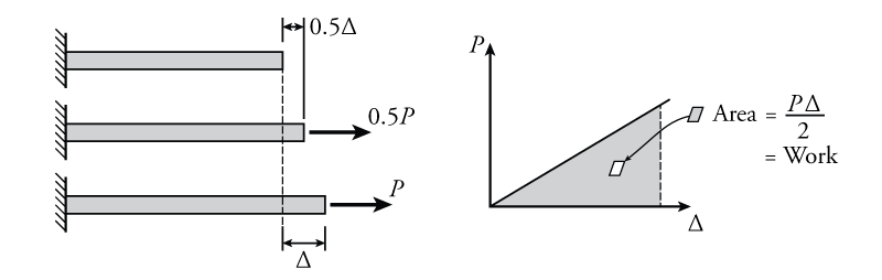
A much more common type of work that is encountered in structural engineering is work done through the deformation of structural parts. An example of this for a simple bar is shown in Figure 5.15. If a load is gradually applied to the bar in tension, as shown in the figure, then the displacement of the right side of the bar also increases gradually (in proportion to the increasing applied force). If the material is elastic, then the displacement is linearly related to the force as per Hooke's Law:
\begin{equation} F = kx \tag{3} \end{equation}
Where $F$ is the force, $k$ is the axial stiffness, and $x$ is the deformation of the bar. Recall that this is a compatibility relationship (see Section 1.4). In our terms, where the force is $P$ and the deformation of the bar is equal to the displacement of the right side of the bar $\Delta$:
\begin{equation} P = k \Delta \tag{4} \end{equation}
The plot of this relationship is shown on the right side of the figure. As was the case was for the body being pushed, the work done in displacing the right end of the bar is equal to the area under the force versus displacement plot as shown:
\begin{equation} W = \frac{P\Delta}{2} \tag{5} \end{equation}
Notice that this is similar to the general work equation from equation \eqref{eq:work}, but is divided by two because the area under the plot is a triangle instead of a rectangle. This new equation for work is applicable when the displacement is linearly proportional to the added force $P$ (i.e. when the force is directly causing a deformation).
+The work caused by the external force ($P\Delta$) in Figure 5.15 is called the external work (here written as $W_e$). In any closed system, energy can never be created or destroyed (recall the Law of Conservation of Energy from physics). Since work is a type of energy, any external work energy that is applied must to go somewhere. In a structural system that is deformed slowly, the external work energy is typically converted to strain energy in the structural members. This strain energy ($U$) can also be called the internal work (here written as $W_i$). The total strain energy in a simple bar that is deformed axially by a force that gradually increases from zero up to a maximum force $p$ is equal to:
\begin{equation} U = \frac{p\delta}{2} \tag{6} \end{equation}
where $\delta$ is the axial deformation of the bar. Recall (from mechanics) that the deformation of a linear axial element is equal to:
\begin{align} \delta &= \frac{pL}{EA} \tag{7} \\ U &= \frac{p^2L}{2EA} \tag{8} \end{align}
where $L$ is the length of the bar, $E$ is the Young's Modulus of the bar material, and $A$ is the cross-sectional area of the bar. If there is only one bar in the system, then the total internal work (strain energy) in the system is equal to:
\begin{align*} W_i = U = \frac{p^2L}{2EA} \end{align*}
Since energy must be conserved in the system, all of the work that is applied to from the outside, must be balanced by the work done on the inside (through strain energy), so:
\begin{equation} \boxed{W_e = W_i} \label{eq:consv-energy} \tag{9} \end{equation}
+or the external work must equal the internal work. This is true as long as all of the energy in the system is in the form of work and strain energy. It will not apply if some of the energy is kinetic energy (i.e. the structure is moving dynamically at some non-zero velocity) or if some of the energy is dissipated as heat. So, for the system shown in Figure 5.15, the external work is equal to the internal work which is equal to the strain energy in the bar.
For the simple case being discussed above, the force that causes the bar deformation is obviously doing work; however, it is important to note that a force does not have to be directly the cause of a displacement or deformation in order to do work. This point so important to understanding the rest of the chapter ahead that it is worth repeating:
A force on a structure can do work, even if it is just 'along for the ride.' An example of such a case is shown in Figure 5.16. In this figure, first a force $P$ is gradually added to the bar. The external work done by this force up to a deformation of $\Delta_P$ is equal to:
\begin{equation*} W_{P0,e}=\frac{P \Delta_P}{2} \end{equation*}
where $\Delta_P$ is the deformation of the bar caused by force $P$. This is the light shaded triangular area in the top right plot of Figure 5.16. This is the same as the work applied previously that was shown in previous Figure 5.15.
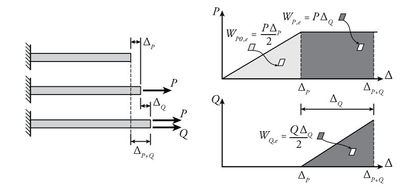
What if we now add another force to the bar (new force $Q$ shown in Figure 5.16) while keeping the original force $P$ constant? The external work done by the addition of force $Q$, which gradually increases from zero up to its maximum value, is similar to the original work that was done by force P when it was applied:
\begin{equation*} W_{Q,e}=\frac{Q \Delta_Q}{2} \end{equation*}
This is the dark shaded triangular area in the bottom right plot of Figure 5.16. There is nothing peculiar about this; however, when the force $Q$ deforms the bar by an additional amount $\Delta_Q$, the original force $P$ continues to do work as the bar is deformed, even though the force $P$ has not changed and even though it is not causing the change in the deformation. The amount of work done by $P$ in this situation, as Q is gradually applied, is not the same as it would have been if it was $P$ that caused the new deformation. Since the force $P$ is constant the entire time that force $Q$ is applied to the bar, the additional external work caused by force $P$ is equal to:
\begin{align*} W_{P,e} = P \Delta_Q \end{align*}
or the force $P$ multiplied by the deformation caused by $Q$. This is the dark shaded rectangular area in in the top right plot of Figure 5.16. Notice that for this type of work (where the force doesn't cause the deformation), there is no more factor of $\frac{1}{2}$ in the work equation (since the area is rectangular instead of triangular). This distinction will be important in the development of the principle of virtual work.
The Principle of Superposition
One more concept that we need to understand before we can talk about the method of virtual work is the principle of superposition. In brief, the principle of superposition says that, for a linear structure, the effects of different loads and actions may be determined separately and then superimposed (added together) to determine the complete behaviour of the structure.
This concept is demonstrated in Figure 5.17. A simple beam structure is shown in part (a) of the figure. This beam has two loads. The full solution for the beam, including the displaced shape is shown on the right side of the figure part (a).
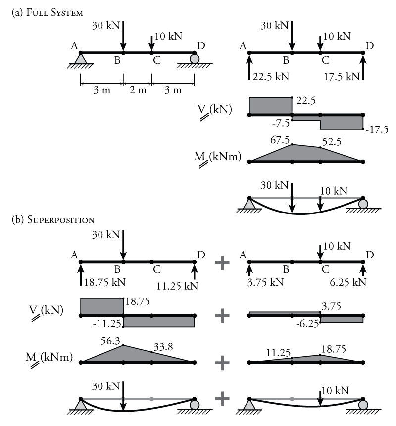
Part (b) of Figure 5.17 shows the same beam structure, but this time the two point loads are applied separately and a full analysis is done for each, including determination of the displaced shape. The figure shows that the complete solution for the structure in part (a) may be found by adding together the two separate solutions in part (b). If the shears from the two parts are added at each location along the beam, then the full shear response would be the result. The same is true for the moment. Try adding together the moments at points B and C on the beam in part (b) to see that you get the total moment in part (a) at those locations. Perhaps most importantly, the same is also true for the displaced shape. If the displaced shape of the structure subjected to all the loads is represented by the function $\Delta_{total}(x)$ and the displaced shape for each individual load is represented by $\Delta_1(x)$ and $\Delta_2(x)$, then:
\begin{equation} \Delta_{total}(x) = \Delta_1(x) + \Delta_2(x) \tag{10} \end{equation}
and in general for any number of loads or load effects:
\begin{equation} \Delta_{total}(x) = \sum_{i=1}^n \Delta_i(x) \tag{11} \end{equation}
The principle of superposition is useful because it means that we can analyse a structure subject to individual loads and then sum all of the resulting shears, moments and deflections to find the total response (instead of having to analyse the structure for all of the loads at once). This comes in handy for the application of virtual work as will be discussed below.
Development of the Principle of Virtual Work
There are two different principles of virtual work, one for rigid bodies, and one for deformable bodies. The principle of virtual work for rigid bodies is akin to equilibrium, but is beyond the scope of this text.
The principle of virtual work for deformable bodies says that the external virtual work applied to a structure must equal the internal virtual work that is caused within the structure:
\begin{equation} \boxed{W_{v,e} = W_{v,i}} \label{eq:virtual-work} \tag{12} \end{equation}
From the previous section we are familiar with the idea that the external work should equal the internal work (because of conservation of energy), but what is `virtual' work?
The development of the principle of virtual work will be demonstrated using the example structure shown in Figure 5.18. Similar to the situation described in previous Figure 5.16, in this structure, there is a single bar with a pin at one end and a roller at the other. This time, the bar is on an angle with respect to the horizontal, and the pin and roller at either end cause it to act like a truss member (i.e. it can only resist axial loads). The bar is on an angle to show that the principle of virtual work applies even if the external load and displacement are not equal to the internal axial load and deformation. Like the previous example, this structure has two loads. One $P_v$ which is added first, and another one $P_r$ that is added after the full application of $P_v$.
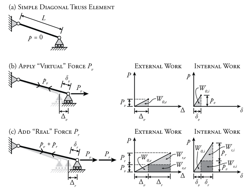
The first stage in the analysis is to add force $P_v$ as shown in Figure 5.18 part (b). This will be the force that we will consider to be our `virtual' force. Once this virtual force $P_v$ is added, it has done external work $W_{0,e}$ on the bar by displacing the roller support at the right end horizontally by an amount $\Delta_v$. The plot of the external force versus displacement as $P_v$ is applied is shown in the figure (top left plot). Since the bar is on an angle, the internal axial force ($p_v$) and axial deformation ($\delta_v$) in the bar are not the same as the applied external force ($P_v$) and displacement ($\Delta_v$). The internal work $W_{0,i}$ (strain energy) in the bar is shown in the top right plot in the figure. The bar force is higher than the external force (because of the angle), and the deformation of the bar will be less than the displacement (also because of the angle, try out the trigonometry for yourself); however, the external work must still be equal to the internal work to maintain the conservation of energy:
\begin{align*} W_{0,e} &= W_{0,i} \\ \frac{P_v \Delta_v}{2} &= \frac{p_v \delta_v}{2} \end{align*}
So, the lightly shaded area under the top left plot must equal the area under the top right plot.
Now, if the 'virtual' force $P_v$ is held constant, what happens if we apply a new force $P_r$? The addition of this new force is shown in Figure 5.18 part (c). We will consider this new force to be our 'real' force. As this new force $P_r$ is gradually applied, it displaces the roller support to the right by an additional $\Delta_r$ as shown. As it does this, the force $P_r$ does an amount of external work of $W_{r,e}$ and a corresponding internal work of $W_{r,i}$ as shown by the newly-added lightly shaded triangles in the bottom left and bottom right plots. Again, the internal and external work done by $P_r$ must be equal to each other due to conservation of energy:
\begin{align*} W_{r,e} &= W_{r,i} \\ \frac{P_r \Delta_r}{2} &= \frac{p_r \delta_r}{2} \end{align*}
While the force $P_r$ is doing work, displacing the end and deforming the bar, force $P_v$ is still present, and therefore also still does work (even though it is not causing the new displacement $\Delta_r$). This work is shown as the dark shaded regions in the plots on the right side of Figure 5.18 part (c). Since the 'virtual' force $P_v$ is constant while the 'real' force $P_r$ is being applied, the external and internal work cause by that force are equal to:
\begin{equation} W_{v,e} = P_v \Delta_r \tag{13} \end{equation}
and
\begin{equation} W_{v,i} = p_v \delta_r \tag{14} \end{equation}
These equations do not have the factor of $\frac{1}{2}$ since the areas are rectangles as shown in the darkly shaded portions of the bottom left and bottom right plots (the force remaining constant). These rectangular areas provide the expressions for the external virtual work and internal virtual work, respectively for this bar. The external virtual work is equal to the virtual external force ($P_v$) multiplied by the real external displacement ($\Delta_r$) and the internal virtual work is equal to the virtual internal force ($p_v$) multiplied by the real internal deformation ($\delta_r$).
Recall that we are trying to demonstrate here the principle of virtual work, which says that the external virtual work applied to a structure must equal the internal virtual work that is caused within the structure (equation \eqref{eq:virtual-work}).
It almost goes without saying at this point that the total external work for the entire system shown in Figure 5.18 part (c) must be equal to the total internal work for the system due to conservation of energy. This means that the total area under the big triangle for the lower left plot in the figure must be equal to the area under the big triangle in the lower right plot. That total work consists of three components, the work done by 'virtual' force $P_v$ when it is applied (the light-shaded triangle on the left of the plot), the work done by 'real' force $P_r$ when it is applied (the light-shaded triangle on the top of the plot), and the 'virtual work' done by 'virtual' force $P_v$, which remains constant as the real force $P_r$ is applied. We have already established that the internal and external work are equal for the two types of triangles caused by the application of forces $P_v$ and $P_r$. Therefore since the total must be equal, then the internal virtual work must equal the external virtual work:
\begin{align*} W_e &= W_i \\ W_{0,e} + W_{v,e} + W_{r,e} &= W_{0,i} + W_{v,i} + W_{r,i} \\ \text{but} \; W_{0,e} &= W_{0,i} \\ \text{and} \; W_{r,e} &= W_{r,i} \end{align*}
Therefore,
\begin{equation*} W_{v,e} = W_{v,i} \end{equation*}
which is the principle of virtual work introduced previously in equation \eqref{eq:virtual-work}. This is also called the virtual work balance equation.
Application of Virtual Work
So, now that we have developed this concept of virtual work, how does that help us to find displacements of structures? Why is the virtual force called 'virtual'? What does any of this mean, anyway?
Let's start with the 'virtual' part first. The force is 'virtual' because we will use that force as kind of a place-holder or tag, so that we can keep track of what is going on at the position on the structure where the force is applied. The magnitude of the force doesn't matter for the principle of virtual work to apply.
So if the virtual force is a tag, what is it tagging? We can use the virtual force to tag some location on a real structure where we want to know a displacement. This real structure has some real geometry and also some set of real forces. The structure with the real forces may be called the real system and the structure with only the virtual force (without the real forces) may be called the virtual system.
The key to the application of virtual work is that we can consider the real and virtual systems separately, of course, but we can also consider both the real and virtual forces acting on the system simultaneously by simply adding the effects of the real and virtual loads by applying superposition (as long as the system is linear). In a virtual work problem, we have three different sets of loads for the structure:
- The real system - the structure with all of the real loadings
- The virtual system - the same structure but with a single virtual load or point moment
- The combined system - this the the superposition of the real and virtual systems where the virtual load is applied first, and then the real loadings are applied after (similar to the situation shown in Figure 5.18).
+If we assume that the virtual load is applied first in the combined system, then based on the development of the principle of virtual work in the previous section, we can consider the effect of both the real and virtual forces on the combined system. We know from equation \eqref{eq:virtual-work} that:
\begin{align*} W_{v,e} = W_{v,i} \end{align*}
where the internal virtual work $W_{v,i}$ is the sum of all the virtual internal forces multiplied by the real internal deformations that are associated with each internal force, and the external virtual work $W_{v,e}$ is the virtual external load multiplied by the real external displacement at the same location and in the same direction where that load is applied. Although the internal and external virtual work both include real and virtual components, we can find the individual component using the real system and virtual system in isolation (again because of superposition). We can find the virtual internal forces and virtual external load from the virtual system and we can find the real internal deformations and real external displacement using the real system.
Notice the the definition of the internal virtual work and external virtual work in equation \eqref{eq:virtual-work} both represent a product of virtual and real components. This is because they both represent the equivalent of the rectangular shaded regions in Figure 5.18(c). For example, the external virtual work is the product of the virtual external load ($P_v$ in the figure) multiplied by the real external displacement ($\Delta_r$ in the figure).
The definition of the external virtual work is what makes the principle of virtual work useful for finding structural deflections. Since the behaviour of the virtual system does not affect the behaviour of the real system, then we can choose any arbitrary set of virtual external loads that we want (position, magnitude and direction). These external virtual forces will be multiplied by real external deflections that are in the same location and direction as the external force. The deflections are what we would like to find. So, if we choose a single external virtual force and locate it in the position and direction where we want to find a single displacement, then we can solve for that single displacement directly using virtual work.
Of course to solve for that displacement, we also need to know the value of the internal virtual work. So that means that we have to find all of the virtual internal forces and the real internal deformations. If we can find these, and if we select an appropriate virtual external load, then we can use virtual work to solve for the real external displacement at a specific point.
To summarize:
\begin{align*} W_{v,e} &= W_{v,i} \\ \text{External Virtual Work} &= \text{Internal Virtual Work} \end{align*} \begin{equation} \boxed{ \sum \left( \begin{array}{l} \text{Virtual Ext. Forces} \; \times \\ \text{Real Ext. Deflections} \end{array} \right) = \sum \left( \begin{array}{l} \text{Virtual Int. Forces} \; \times \\ \text{Real Int. Deformations} \end{array} \right) } \tag{15} \end{equation}
Finally, an example of what each of these components actually look like for a beam is shown in Figure 5.19. The goal of this analysis is to find the vertical deflection of the cantilever at point B on the real system shown on the left side of the figure. This unknown deflection is the real external deflection for our virtual work balance. To find this real external deflection, we need to construct an appropriate virtual system with a single load in the same location and in the same direction as the real deflection that we are trying to find. The appropriate virtual system is shown on the right side of the figure. The virtual work done by this load will be equal to the magnitude of the load multiplied by the real external deflection (with no factor of $\frac{1}{2}$ because remember that we are assuming that the virtual load is applied first and does that work while the real loads are applied).
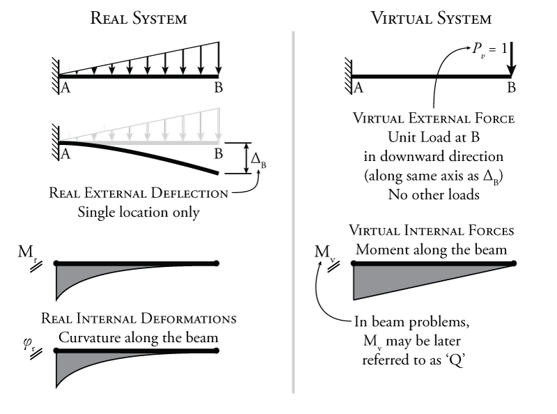
+Now we have the external virtual work, we also need the internal virtual work. A frame element, unlike the truss bar element that we discussed previously, has multiple different ways to store strain energy. In addition to axial strain (like the bar), a frame element can also store strain energy as bending strain and shear strain. For beam bending problems like this, the axial and shear deformations are typically insignificant in comparison to the deformations caused by bending stresses and strains. So, for a problem like this, we can get a very good estimate of the deflection by only considering the internal virtual work done by bending stresses. For that calculation, we need the virtual internal forces (in this case, the moment at every point on the virtual beam) and the real internal deformations (in this case, the slope at every point on the real beam, which can be found by integrating the curvature). To find the sum for the internal virtual work in this case, we have to integrate over the length of the beam:
\begin{align*} W_{v,i} &= \sum \left( \text{Virtual Int. Forces} \; \times \text{Real Int. Deformations} \right) \\ W_{v,i} &= \int \phi_r(x) M_v(x) \, dx \end{align*}
where $\phi_r(x)$ is the curvature in the real beam, which is known based on the real loading, and $M_v(x)$ is the moment in the virtual beam, which is also known based on the virtual loading.
Now applying the principle of virtual work:
\begin{align*} W_{v,e} &= W_{v,i} \\ P_v \Delta_B &= \int \phi_r(x) M_v(x) \, dx \\ \Delta_B &= \frac{\int \phi_r(x) M_v(x) \, dx}{P_v} \end{align*}
As mentioned previously, since the virtual system is arbitrary, we can select any magnitude for the virtual force that we want. So, it's convenient to select a unit value of 1, so that the unknown real external deflection is simply equal to the internal virtual work:
\begin{align*} \Delta_B = \frac{\int \phi_r(x) M_v(x) \, dx}{1} \end{align*}
The full methods for calculating internal virtual work for truss systems and beam/frame systems will be discussed in the following sections.