Learn About Structures
The portal method is based on the assumption that, for each storey of the frame, the interior columns will take twice as much shear force as the exterior columns. The rationale for this assumption is illustrated in Figure 7.3.
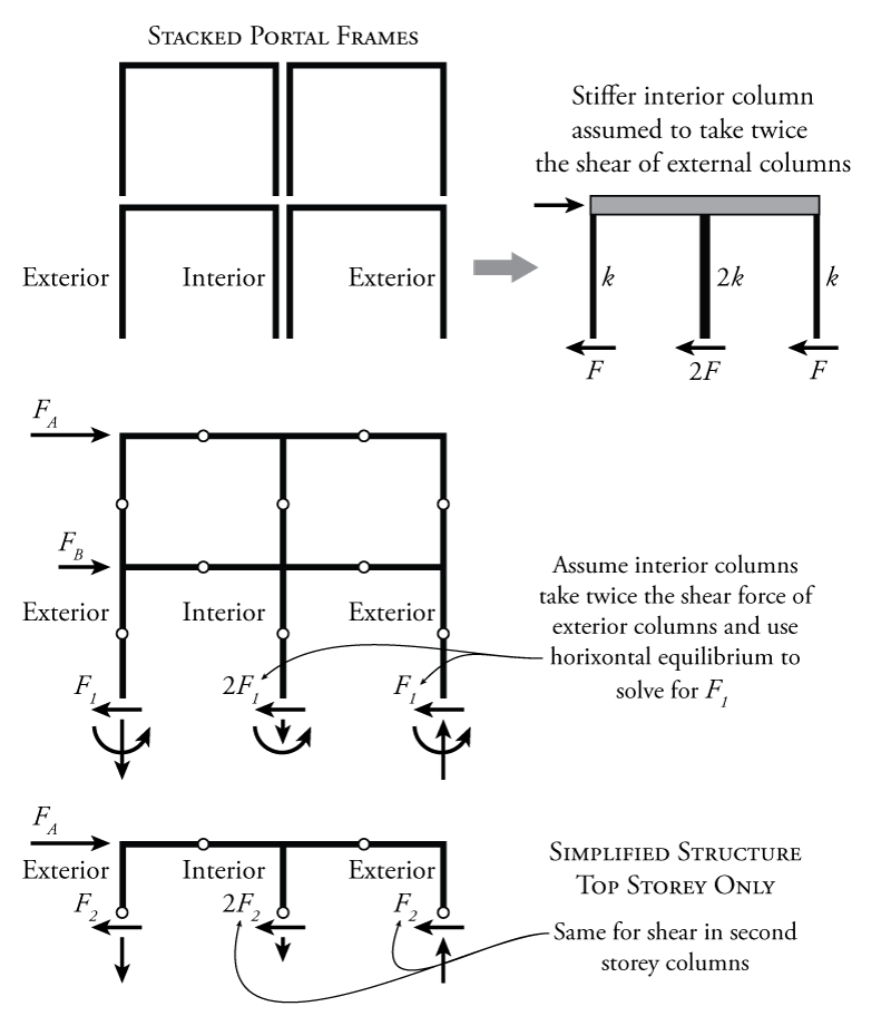
Let's consider our multi-storey, multi-bay frame as a series of stacked single storey moment frames as shown at the top of Figure 7.3. The columns on either end of each individual portal frame are likely similar size because they would each equally share the gravity load from above. When we join these all together into a stacked system, we can see, as in the figure, that the interior columns have two portal frame columns each since they need to take axial force from the left and from the right (whereas the exterior columns only take gravity loads from the left or right). So, if we combine all of these individual portal frames together, our interior column (the sum of the two individual portal frame columns) will need to be twice as strong as the exterior columns.
If the interior columns are twice as strong, they may also be approximately twice as stiff (as shown in the diagram at the top right of Figure 7.3). If we then have three columns in parallel as shown and they all share the total lateral load at the top as shown, then they will resist the total load in shear in proportion to their relative stiffness. A column that is twice as stiff will take twice as much load for the same lateral displacement.
So, it may be reasonable to assume that, since the interior columns are approximately twice as big, and therefore twice as stiff, as the exterior columns, those interior columns will take twice as much shear as the exterior columns. This is the basis of the portal method assumption.
This assumption is valid for the columns at every storey as shown in Figure 7.3. So, the portal method provides us with the shear force in each column at each storey in the structure. In our example structure, for any given free body diagram cutting at the hinge location at a single storey, the system will be ${2^\circ}$ indeterminate. If we know the shear in the middle column in relation to the shear at the left column, that eliminates one unknown (we assume the middle column has twice as much as the left column $2F_1$). If we know the shear in the right column in relation to the shear at the left column, that eliminates another unknown (we assume they are equal). These two assumptions eliminate the remaining $2^\circ$ of static indeterminacy, meaning that we can find the rest of the unknowns using the equilibrium equations only. The portal method assumptions do not give us three known forces because we still have to solve for the force in the left column using horizontal equilibrium before we can use that force to find the forces in the middle and right columns.
Example
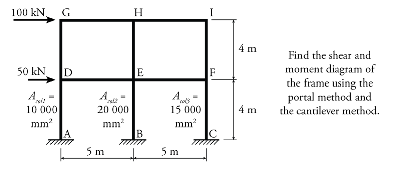
An example indeterminate frame that may be solved using the portal method is shown in Figure 7.4. The column areas are given for use with the cantilever method which will be discussed in the next section. For now we will only analyse this structure using the portal method.
The first step in the portal method analysis is to add hinges at the centre span or height of all the beams and columns (except for the lower storey if the column bases are pinned), and then determine the column shears at each storey using the portal method assumptions. This process is illustrated in Figure 7.5. The new hinges are shown in the figure at points a through j.
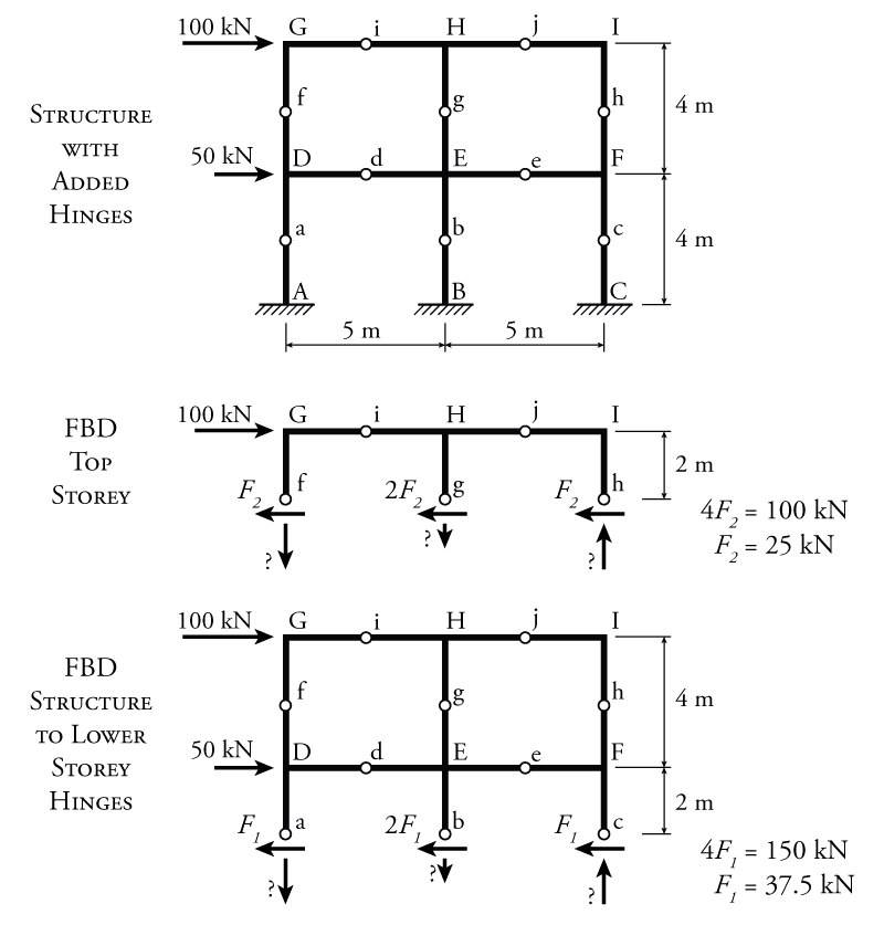
To determine the column shears for each storey, two different section cuts are made. For the top storey (shown in the middle of Figure 7.5), a section cut is made through the hinges at points f, g, and h (although for the portal method, this cut could be anywhere along the height of the storey when finding the column shear). To find the shear force in the left column ($F_2$), the force in the middle column is assumed to be equal to twice the force in the left column ($2F_2$ since it is an interior column) and the force in the right column is assumed to be equal to the force in the left column ($F_2$). Then, using horizontal equilibrium applied to the whole free body diagram of the top storey:
\begin{align*} \rightarrow \sum F_x &= 0 \\ 100 - F_2 - 2F_2 - F_2 &= 0 \\ 4F_2 &= 100 \\ F_2 &= 25\mathrm{\,kN} \leftarrow \end{align*}
Therefore, the shear in the exterior columns in the second storey is $25\mathrm{\,kN}$ and the shear in the interior column is $50\mathrm{\,kN}$. For the lower storey (shown in the bottom of Figure 7.5), a section cut is made through the hinges at points a, b, and c. Similarly:
\begin{align*} \rightarrow \sum F_x &= 0 \\ 100 + 50 - F_1 - 2F_1 - F_1 &= 0 \\ 4F_1 &= 150 \\ F_1 &= 37.5\mathrm{\,kN} \leftarrow \end{align*}
Therefore, the shear in the exterior columns in the first storey is $37.5\mathrm{\,kN}$ and the shear in the interior column is $75\mathrm{\,kN}$.
Now that we know the column shears, the rest of the analysis uses only equilibrium to find the rest of the forces in the frame. To do so, the entire frame is cut into separate pieces at every hinge location. This is useful because each piece of the structure between the hinges can be analyse with the knowledge that the moment at the hinge is always zero. This process is illustrated in Figure 7.6.
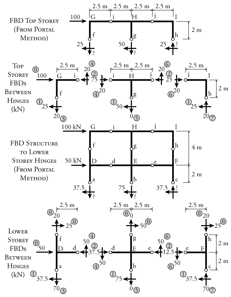
To analyse the frame, it is helpful to start at the top of the structure and work our way down. The previous free body diagram of the top storey from Figure 7.5 with the known column shears is shown at the top of Figure 7.6. This free body diagram is further split into three pieces as shown directly below, cutting the storey apart at the hinge locations in the beams (at points i and j). The numbers that are shown in grey circles provide a suggested order for the analysis that will be described here. This is not the only order that is possible, there are many ways to solve this structure. The goal of this analysis is to find all of the unknown vertical and horizontal loads at the hinge locations. The force for step 0 is a given: don't forget to include the external lateral load of $100\mathrm{\,kN}$. Step 1 loads are from the portal method analysis, giving the column shears for each column at points f, g, and h (the results of which are shown at the top of the figure). Now that all of the previously known forces are included on the free body diagrams, we can use equilibrium to find the remaining unknowns. In step 2, we can use horizontal equilibrium for the left free body diagram to find the horizontal load at point i to be equal to $75\mathrm{\,kN}\leftarrow$. Don't forget that on the other side of the cut at point i (the right side) the horizontal force at point i must point in the opposite direction ($75\mathrm{\,kN}\leftarrow$). At the same time in step 2, horizontal equilibrium of the middle free body diagram for the top storey can be used to find the horizontal load at point j (which is also in opposite directions on either side of the cut at j). In step 3, moment equilibrium around point i may be used to find the vertical load at point f. In step 4, vertical equilibrium is used to find the final unknown for the left free body diagram, the vertical load at point i. Don't forget to transfer that load to the other side of the cut at point i. Like the horizontal load, the vertical load on the other side of the cut at point i must point in the opposite direction. Moving onto the middle free body diagram for the top storey, in step 5, moment equilibrium about point j is used to solve for the vertical load at point g (which happens to be 0). Then in step 6, vertical equilibrium is used on the middle free body diagram to find the vertical load at point j, which is also transferred in the opposite direction to the other side of the cut. Last, in step 7, vertical equilibrium on the right free body diagram for the top storey is used to find the final remaining unknown, the vertical load at point h. Again, this step-by-step method is not the only order that can be used to solve for the unknowns. The important thing is to look at how you can use some equilibrium equation to solve for one of the remaining unknowns.
For the lower storey, the frame is again cut into three different pieces with cuts being made at the hinge locations (to avoid having any unknown moments in the free body diagrams), as shown in lower diagram of Figure 7.6. This time, step 0 may include the external lateral load of $50\mathrm{\,kN}$ in addition to the forces at points f, g, and h that were previously found using the top storey free body diagrams shown above. At points f, g, and h on the lower storey free body diagrams, the loads from the top storey must be applied in the opposite directions to those from the top storey free body diagrams (because they are on either side of a cut in the structure). Then in step 1, the known column shears from the portal method analysis are applied to points a, b, and c (based on the results from the previous analysis which are shown about the lower storey free body diagrams. Once all of the known forces are included, the rest of the unknown forces may be found using equilibrium as was done for the top storey. Again, one suggested solution order is shown in the figure using numbers in grey circles.
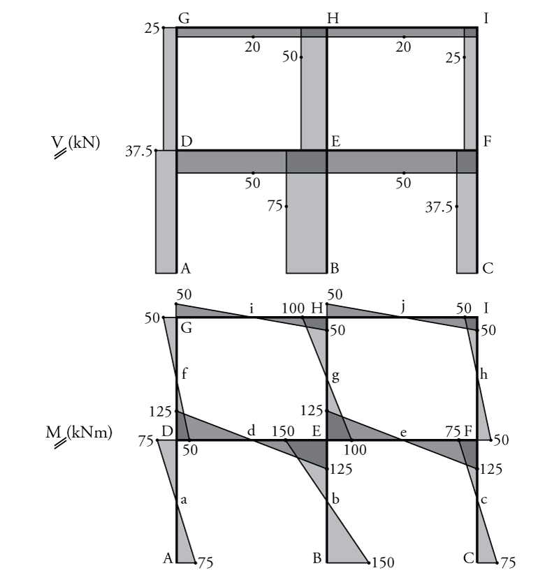
Once all of the forces at the hinge locations are known, the shear and moment diagrams may be drawn for the frame. The resulting diagrams are shown in Figure 7.7. The shear in all of the beams and columns are always constant for these types of analyses, and are simply equal to the horizontal force in the middle hinge for the columns or equal to the vertical force in the middle hinge for the beams. The maximum moment in the beams and columns is then found using the shear multiplied by half of the column height for columns or multiplied by half of the beam length for beams. This is because there is no moment at the hinge. So if we start at the hinge and move towards any beam column intersection, then the moment at the intersection will be equal to the shear multiplied by the distance between the hinge and the intersection. For example, for the moment in column AD at point D, we start with a shear in the column of $37.5\mathrm{\,kN}$ at point a as shown in Figure 7.6, and then the distance between point a and point D is $2\mathrm{\,m}$. This gives a total moment in column AD at point D of $2(37.5)=75\mathrm{\,kNm}$. For the moment in beam HI at point H, we start with a shear in the beam of $20.0\mathrm{\,kN}$ at point j as shown in Figure 7.6, and then the distance between point j and point H is $2.5\mathrm{\,m}$. This gives a total moment in column AD at point D of $2.5(20.0)=50\mathrm{\,kNm}$.