Learn About Structures
External Forces are those which are applied to the boundary of a structure. This includes explicit externally applied forces as well as the forces that are applied by the supports to restrain the structure (as shown in Figure 1.7).
Internal forces are those that are exerted on a portion of a structure by the rest of the structure. You would only see these forces if you were to make a cut in the structure and separate it into two free body diagrams. These are the forces that are represented by member shear and moment diagrams (that will be covered later).
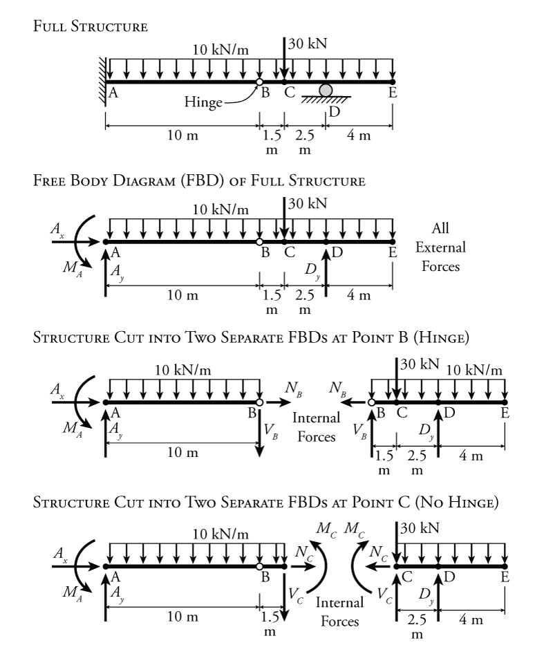
The difference between internal and external forces is illustrated by the sample beam structure shown in Figure 1.7. The top diagram in the figure shows the full structure, including the supports (see Section 1.5). This is not a free body diagram because it does not include all of the forces acting on the system (it is missing the reactions). The full structure is converted to a free body diagram in the second diagram from the top of the figure. This structure has a fixed end at the left (point A) which contributes three unknown reactions: the horizontal and vertical reactions $A_{x}$ and $A_{y}$ and the reaction moment $M_A$. It also has a roller support at point D which contributes only one reaction force $D_{y}$ (perpendicular to the rolling direction). A uniformly distributed load of $10\mathrm{\,kN/m}$ is applied to the entire length of the beam. This means that for every metre of beam length, $10\mathrm{\,kN}$ of force is spread out evenly across that length. In addition, an extra point load of $30\mathrm{\,kN}$ is applied at Point C in the downwards direction. The beam structure also has a hinge located at point B. This hinge allows the beam to rotate freely on either side of point B (just like a door hinge). Since the hinge can rotate freely, there cannot be any internal moment at point B. In the free body diagram of the full structure, all of the forces shown are external forces, meaning that they are applied to the boundary of the structure (the outside). These external forces include both the reactions forces at the supports and the distributed/point loads.
The lower two diagrams in Figure 1.7 show the internal forces at two different points on the beam (points B and C). In order to investigate the internal forces, we must separate the structure into two separate parts, each with a separate free body diagram. The forces/moments on either side of the cut must be equal and opposite in direction for the two separate pieces. This is required by equilibrium. For the separation at point B, the structure is being cut at the location of the hinge. The hinge cannot transfer any moment from one side of the cut to the other (since it has no resistance to rotations). Therefore, there are only two forces at the cut for the hinge, a vertical force and a horizontal force. The vertical force $V_B$, which is perpendicular to the beam, represents the shear force within the beam at point B. On the left side of the cut, $V_B$ points down, and on the right side it points up. These are in the opposite direction and have the same magnitude ($V_B$). The horizontal force $N_B$, which is parallel to the beam length, represents the axial force (tension or compression) within the beam at point B. On the left side of the cut, $N_B$ points to the right, and on the right side it points to the left. Again, they point in opposite directions and have the same magnitude. As they are drawn here, they would represent a tension force in the beam (since the arrows are pulling on the ends of the beam at the cut). If the arrows were both in the reverse direction, they would represent a compression in the beam.
If the structure is cut at point C (the bottom diagram in Figure 1.7), then there are three unknown internal forces at the cut, $V_C$, $N_C$ and the bending moment $M_C$. Since there is no hinge at point C, the beam can transmit moment through the beam at that point. The axial force and shear force at point C point in opposite directions as before on either side of the cut. The moments are also in opposite directions on either side of the cut, being drawn counter clock-wise on the left side, and clock-wise on the right side. At point C, there is also a point load of $30\mathrm{\,kN}$. When the structure is cut at point C, the point load must be located on one side of the cut or the other, but cannot be located on both free body diagrams. If the point load is located on the right side of the cut (as shown in the figure), then the internal shear force $V_C$ will be the shear force to the left of the point load. If the point load was located on the left side of the cut, then $V_C$ would be the shear on the right side of the point load. This is important to clarify, because the point load instantaneously changes the shear at point C, so it is meaningless to talk about the shear right at point C. It is only meaningful to talk about the shear immediately to the left or right side of it. This is also true if a cut is being made at a reaction load location (caused by a support). From the point of view of the beam, there is no difference between an applied point load or a reaction load. They are both just external forces. The moment and axial force at point C will be the same regardless of which side of the cut the point load gets put on.
Force and Moment Notation
For forces at a point, unknown external forces will be shown as $A_y$ where $A$ is the point at which the force acts and $y$ is the direction (typically $x$-direction horizontal, $y$-direction vertical) as shown for the forces in Figure 1.7. To further specify where a force acts, for example, at a cut in a structure such as those shown, a force may also be shown as $B_y^{AB}$ for the vertical force that acts at the cut on the side of member AB or $B_y^{BC}$ for the vertical force acting on the other side of the cut on member BC. This would be an alternate way to show the internal shear force $V_B$ in Figure 1.7. At a cut these forces will have the same magnitude but opposite directions (for example, one would point up and the other would point down); however both forces at a cut are manifestations of the same shear force at that point in the structure.
For moments, the situation is the similar, except that in the notation $M_A$, $M$ just means moment and $A$ is the point at which that moment acts. There is no need to specify a direction because in a 2D plane, all moments act around the $z$-axis. Like, forces, moments may be identified on either side of a cut using the notation $M_C^{BC}$ and $M_C^{CD}$ for moments on either side of the cut at C shown in Figure 1.7.
Sign Conventions
There are two different types of sign conventions that we will be concerned with in structural analysis.
External Forces (or those applied to an FBD)
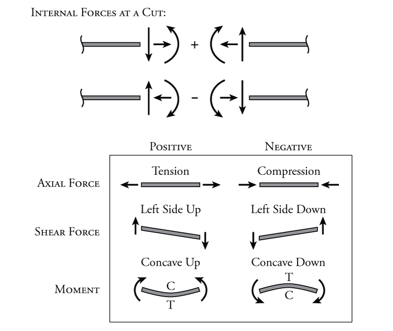
The first sign convention is for external forces. This may include forces that are caused by internal forces but which are applied at a cut in the structure (on a free body diagram). The sign convention for point forces is shown in Figure 1.8. In these notes, forces towards the right ($\rightarrow$) will be considered positive and so will forces that point up ($\uparrow$). Accordingly, forces that point to the left ($\leftarrow$) or down ($\downarrow$) will be considered negative. For moments, as discussed previously, counter clock-wise (CCW $\curvearrowleft$) rotations will be considered positive and clock-wise rotations (CW $\curvearrowright$) will be considered negative.

Internal Forces
The sign convention for internal forces is more complex. This is because for internal forces (the forces in a structure at a cut), the forces on either side of the cut must be equal, but in opposite directions (see Figure 1.7). For example, for the shear at point B in Figure 1.7 $V_B$, the force on the left side of the cut (which could be called $V_B^{AB}$) points down (negative), but the force on the right side of the cut ($V_B^{BC}$) points up (positive). Is this equivalent to a positive or negative internal shear at point B? The situation is similar for the axial force at point B ($N_B$) and the moment shown at point C (on the left side $M_C$ is CCW positive and on the right side it is CW negative). As these are shown would they be positive or negative axial force and moment?
The sign convention for the internal forces is effectively arbitrary. It doesn't matter which way we define the internal forces to be positive or negative, as long as we are consistent. The sign conventions for internal forces that will be used in these notes are shown in Figure 1.9. As the figure shows, the positive sense for axial force (tension) will have a different arrow direction depending on which side of the cut you are looking at. For positive axial force, the arrow will always point away from the member. Likewise, for negative axial force (compression), the force will always point towards the member at a cut or at a member end. Shear force is a bit more difficult, positive shear is created by a pair of vertical forces which cause a member to shear such that the left side of the member is pushed up and the right side of the member is pushed down. If the structural member is oriented so that it is vertical, then positive shear may be defined such that the shear is positive if the lower side is pushed to the left, but this may not always be the most convenient way to define positive shear for a vertical member, which will be seen later on. For moment, the easiest way to think about it is that for positive moment, the compression side of the member is on top (recall that when a structural member bends, one side is put into tension and the other side is put into compression). For a horizontal member in positive bending, it will bend such that the shape of the member is concave up as shown in the figure. Note that whether the member is in positive or negative moment, the moment arrow will always point towards the compression side of the member.