 Learn About Structures
A boundary condition is a place on a structure where either the external force or the displacement are known at the start of the analysis. In this way, boundary conditions are where the structure interacts with the environment either through the application of an external force or through some restraint that is imposing a displacement. For a structural analysis problem to be solvable, every location on the boundary of our structure must have a known boundary condition, either a known force or a known displacement. The known force or displacement may have some magnitude or it may be zero. For example, we may know that there are locations on our structure that have no external force. This would be a zero force boundary condition. A displacement boundary condition that is zero is equivalent to the structure being held in place at that location.
Degrees of Freedom
Boundary conditions are typically expressed in terms of applicable degrees of freedom. A degree of freedom (DOF) is simply a single direction that a point on a structure can move freely. In two dimensions (2D), each free point on a structure has three different possible DOFs: one horizontal, one vertical, and one rotational. This means that a point can move (translate) in the x-direction and y-direction, or can rotate about the out-of-plane z-axis (equivalent to rotating within the 2D plane). These are the same three directions that were previously used for the equilibrium expressions in equation \eqref{eq:Equil2D}.
\begin{equation}\label{eq:Equil2D} \tag{1} \boxed{ \sum_{i=1}^{n}{F_{xi}} = 0; \sum_{i=1}^{p}{F_{yi}} = 0; \sum_{i=1}^{q}{M_{zi}} = 0 } \end{equation}
In three dimensions (3D), each free point has six DOFs, three translational and three rotational as shown in Figure 1.4.

Restraints and Supports
The most common displacement boundary conditions in structural analysis are those that restrain the movement of the structure in one or more degrees of freedom at a point. These restraints are also called supports. At these restraint locations, we know that the displacement of the structure in each restrained degree of freedom is zero; however, we don't know what force is necessary to hold the degree of freedom in that restrained position. This force is called the reaction force or reaction.
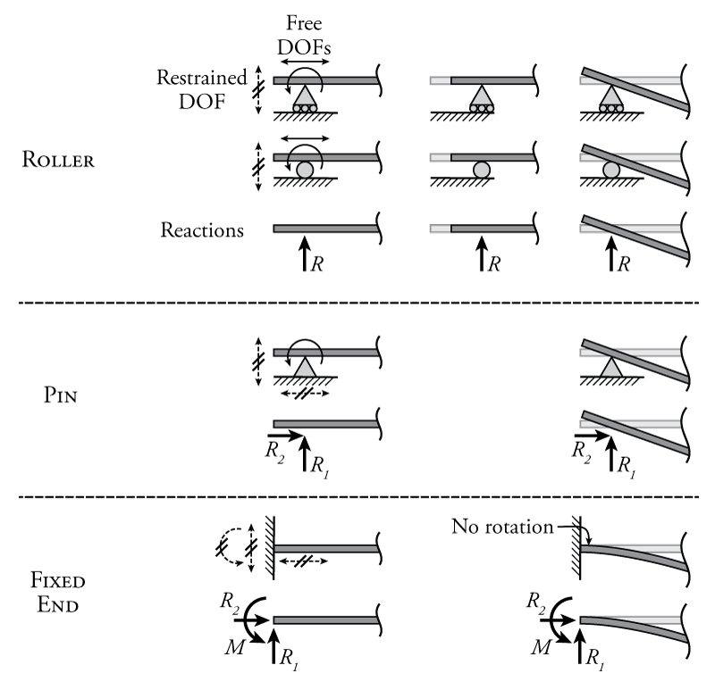
The three most common types of supports in 2D are shown in Figure 1.5. The first type, a roller, can only restrain the structure in one DOF, the DOF that is perpendicular to the rolling direction, as shown. The roller allows translation parallel to the roller support plane and also allows rotation at that point. There are two ways of showing a roller, either as a circle, or as a triangle supported on smaller circles, they both mean the same thing. Since there is one restrained DOF, there is also one reaction force at a roller support which is in the same direction as the restraint.
The second common type of support shown in Figure 1.5, a pin, restrains two DOFS, both of the translation directions. A pin effectively restrains the structure in place at the support point, but allows it to rotate around that point. +Since there are two restrained DOFs, there are two associated reaction force components, one in each translational direction.
The third common support type is the fixed end, which restrains the structure in all DOFs, translational and rotational. This results in three reaction components, two of which are forces, and a third which is a moment reaction (the moment that is necessary to restrain the rotation). The deformed structure connected to the fixed end at the bottom right of the figure is intended to show that even though the structure may deform near the fixed end, at the end itself there is no rotation.
In addition to the common supports described above, more complex support conditions are also possible as shown in Figure 1.6. These support restraints are like the fixed restraint described above, but with one of the translations released.
