 Learn About Structures
The equilibrium equations in \eqref{eq:TrussEquil} define forces in terms of x- and y- directions.
\begin{equation}\label{eq:TrussEquil} \tag{1} \sum_{i=1}^{n}{F_{xi}} = 0; \sum_{i=1}^{p}{F_{yi}} = 0; \end{equation}
Truss members are often inclined relative to the horizontal as shown in Figure 3.2.
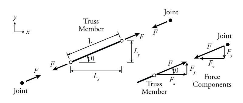
This figure shows a free body diagram of a truss member in tension with the forces at either end of the member parallel to the member itself and pointing away from it. Using our sign convention, this represents a positive axial force. The truss member axial forces ($F$ in the figure) are typically the unknown forces that we are trying to calculate in a truss analysis. As previously discussed in Section 1.6, although there is a sign convention for the internal axial force itself (positive for tension, negative for compression), in our solution, we will have to consider the actual direction of force arrows (as external forces) in a free body diagram of the member or the connected joints. For the axial force $F$ shown, the force on the left of the member points down and to the left, while the force on the right points up and to the right. These forces in opposite directions together create the internal tension axial force in the truss member.
The free body diagram of the truss member shown on the left side of Figure 3.2 is cut at the location of the hinges at either end; however, at either end of the member, it is connected to a joint, which may be represented as a single point as shown. Note that the joints shown in the figure are not free body diagrams because they are clearly not in equilibrium (unless $F=0$). The force on the joint caused by the truss member is in the opposite direction of the force on the truss member caused by the joint. This follows from Newton's third law and was described previously in Section 1.6, where it was shown that the forces on either side of a cut in a structure must be equal in magnitude and opposite in direction. In a truss analysis, it is important to keep careful track of which way the forces are pointing. In general, a tension force will point away from a truss member end or a joint and a compression force will point towards a member end or joint.
The $x$- and $y$-direction force components of the total force in a truss member, may be found using either the slope of the member or the angle relative to the horizontal (shown as $\theta$ in Figure 3.2).
To use the slope, you need to know the relative lengths $L$, $L_x$ and $L_y$, all of which may be easily found using the geometry of the truss. The lengths $L_x$ and $L_y$ are the projected lengths of the member total length $L$ onto the $x$ or $y$ axes, respectively. The total force and force components are relative to their lengths, so:
\begin{align} \tag{2} F_x = \left( \frac{L_x}{L} \right) F \\ \tag{3} F_y = \left( \frac{L_y}{L} \right) F \end{align}
Often, you know the projected lengths $L_x$ and $L_y$ and can use these to find the total length $L$ using the Pythagorean Theorem:
\begin{equation} \tag{4} L = \sqrt{L_x^2 + L_y^2} \end{equation}
Alternately, the force component may be found using trigonometry and the brace angle $\theta$. Using trigonometry, the force components are simply equal to:
\begin{align} \tag{5} F_x = F \cos \theta \\ \tag{6} F_y = F \sin \theta \end{align}
The angle $\theta$ may be found using trigonometry if it is not given. If the projected lengths $L_x$ and $L_y$ are known, then:
\begin{equation} \theta = \arctan \left( \frac{L_y}{L_x} \right) \label{eq:incl-angle}\tag{7} \end{equation}
In the end, both of these methods are identical, the only difference being that they use different starting information. The most efficient method to use will depend on what information is known at the start of a truss analysis problem. Both methods will work though, regardless of the problem.