 Learn About Structures
The slope-deflection equations give us the moment at either end of each element within a structure as a function of both end rotations, the chord rotation, and the fixed end moments caused by the external loads between the nodes (see Section 9.3).
\begin{equation} \boxed{ M_{AB} = \frac{2EI}{L} (2 \theta_A + \theta_B - 3 \psi ) + \text{FEM}_{AB} } \label{eq:SD-AB} \tag{1} \end{equation} \begin{equation} \boxed{ M_{BA} = \frac{2EI}{L} (\theta_A + 2 \theta_B - 3 \psi ) + \text{FEM}_{BA} } \label{eq:SD-BA} \tag{2} \end{equation} \begin{equation} \boxed{ M_{nf} = \frac{2EI}{L} (2 \theta_n + \theta_f - 3 \psi ) + \text{FEM}_{nf} } \label{eq:SD-NF} \tag{3} \end{equation} \begin{equation} \boxed{ M_{rh} = \frac{3EI}{L} (\theta_r - \psi ) + \left( \text{FEM}_{rh} - \frac{\text{FEM}_{hr}}{2} \right) } \label{eq:SD-RH} \tag{4} \end{equation} \begin{equation} \boxed{ M_{hr} = 0 } \label{eq:SD-HR} \tag{5}\end{equation}
After we have those equations determined, we can apply moment equilibrium equations at each node, i.e. all the moments applied to the node must add to zero. Then we can solve those equations simultaneously to find the end rotations. These end rotations may then be substituted back into the slope-deflection equations to find the real moments at the ends of all of the members. From these moments, we can find the shears and reactions and the moment diagrams for the entire structure.
The entire process for an indeterminate beam is summarized as follows:
- Find all of the unrestrained DOFs in the beam structure.
- Define an equilibrium equation for each DOF (for rotations, the sum of all moments at each rotating node must equal zero).
- Find the moments to put into the equilibrium conditions using the slope deflection equations (either \eqref{eq:SD-AB}/\eqref{eq:SD-BA}/\eqref{eq:SD-NF} for regular members or \eqref{eq:SD-RH}/\eqref{eq:SD-HR} if the element has a pin or hinge at the end). To do this:
- For each element that has an external force between the nodes, find the fixed end moments at either end using Figure 9.6.
- If there are any support settlements or imposed displacements at node locations, find the chord rotations caused by that settlement/displacement.
- Construct each slope deflection equation.
- Put the slope deflection moments into the equilibrium equations and use the resulting equilibrium equations to solve for the values of the unknown DOF rotations (by solving the system of equations).
- Use the now-known DOF rotations to find the real end moments for each element of the beam (sub the rotations back into the slope-deflection equations).
- Use the end moments and external loadings to find the shears and reactions.
- Draw the resultant shear and bending moment diagrams.
Example
The slope-deflection method for beams will be illustrated using the example structure shown in Figure 9.8. This structure is ${4^\circ}$ indeterminate, and so would be difficult to solve using the force method. Nodes A and C are fixed and so do not have any degrees-of-freedom (DOFs). Node B cannot move horizontally since it is restrained by members AB and BC, which are both fixed horizontally. Node B is also restrained from moving vertically due to the roller support at that location; however, node B can rotate. The total rotation of node B is $\theta_B$. Overall, this structure has only one DOF, which means it is a good structure to analyse using the slope-deflection method.
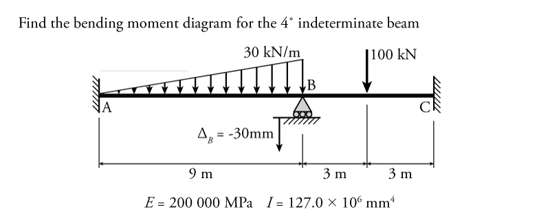
In addition to the external distributed load on member AB and the point load at the centre of member BC, there is a support settlement of $30\mathrm{\,mm}$ downwards at point B.
For the sole rotational DOF at node B, the equilibrium condition will be:
\begin{align*} M_{BA} + M_{BC} = 0 \end{align*}
where $M_{BA}$ is the moment at the end of member AB at node B, and $M_{BC}$ is the moment at the end of member BC at node B. These two moments are the only moments that act at point B. For equilibrium to be maintained, the moments around node B must sum to zero.
The next step is to construct the slope-deflection equations for each member to find an expression for the moment at each end in terms of the end rotations, chord rotation, and fixed end moments. There are two slope deflection equations for each member (one for the moment at each end). We first need to find the chord rotations and fixed end moments for both members, since they are a required input for the slope-deflection equations.
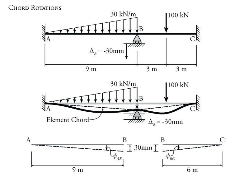
The calculation of the chord rotations for each member are shown in Figure 9.9. When the vertical support at node B settles by $30\mathrm{\,mm}$, it takes point B downwards with it. This results in a rotation of the chord of the member. Recall that the element chord is just a straight line that joins the two ends of the member without regard to the actual deflected shape of the beam, as shown in the figure. The chord rotation for member AB can be found using equation \eqref{eq:chord-rotation}:
\begin{equation} \boxed{ \psi = \frac{\Delta}{L} } \label{eq:chord-rotation} \tag{6} \end{equation} \begin{align*} \psi_{AB} &= \frac{\Delta_B}{L_{AB}} \\ \psi_{AB} &= \frac{30\mathrm{\,mm}}{9000\mathrm{\,mm}} \\ \psi_{AB} &= -0.00333\mathrm{\,rad} \end{align*}
where $L_{AB}$ is the length of member AB. There is only one value for the chord rotation for each element. If we think about the chord of member AB rotating about point A, it rotates clockwise (negative rotation) when the support at B settles downwards. Likewise, if we think about the chord of AB rotating about point B, the element chord still rotates clockwise when the support at B settles (still negative rotation). Similarly, for member BC, the chord rotation is:
\begin{align*} \psi_{BC} &= \frac{\Delta_B}{L_{BC}} \\ \psi_{BC} &= \frac{30}{6000} \\ \psi_{BC} &= +0.00500\mathrm{\,rad} \end{align*}
This time, the rotation of the chord is counter-clockwise when the support at B settles (positive rotation). Both of these chord rotations will be used in the slope deflection equations for the beam elements.
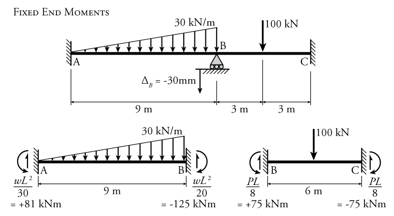
The fixed end moments for each beam element are found using the different scenarios shown in Figure 9.6. Member AB has an external triangular distributed load with a maximum value of $30\mathrm{\,kN/m}$. The fixed end moments for this member with a triangular distributed load are found under the 'Distributed Loads' heading in the figure. The calculation of the fixed end moments for AB using the values from Figure 9.6 are shown in Figure 9.10. The calculation results in a fixed end moment on the left side of the member of $\text{FEM}_{AB} = +81\mathrm{\,kNm}$ (positive because it is counter-clockwise), and on the right side of the member of $\text{FEM}_{BA} = -125\mathrm{\,kNm}$ (negative because it is clockwise). Likewise, for member BC, which has a single point load, the fixed end moments are $\text{FEM}_{BC} = +75\mathrm{\,kNm}$ on the left (CCW) and $\text{FEM}_{CB} = -75\mathrm{\,kNm}$ on the right (CW).
Now we can construct the slope-deflection equations for each beam element. Neither of the beam elements have a pin or hinge at the end, so we will use equation \eqref{eq:SD-NF}. The roller at point B does not count as a pin end since the beam is continuous there (so clearly the internal moment at point B will not be equal to zero). The general slope-deflection equation from equation \eqref{eq:SD-NF} is:
\begin{align*} M_{nf} &= \frac{2EI}{L} (2 \theta_n + \theta_f - 3 \psi ) + \text{FEM}_{nf} \end{align*}
For the moment at the end of member AB at point A, A is the near side and B is the far side, so:
\begin{align*} M_{AB} &= \frac{2EI}{L} (2 \theta_A + \theta_B - 3 \psi_{AB} ) + \text{FEM}_{AB} \\ M_{AB} &= \frac{2EI}{9} (2 \theta_A + \theta_B - 3 (-0.00333) ) + 81 \end{align*}
But, since node A is fixed, then we know that $\theta_A =0$, so:
\begin{equation*} \boxed{M_{AB} = \frac{2EI}{9} (\theta_B + 0.0100 ) + 81 } \end{equation*}
For the moment at the end of member AB at point B, B is the near side and A is the far side, so:
\begin{align*} M_{BA} &= \frac{2EI}{L} (2 \theta_B + \theta_A - 3 \psi_{AB} ) + \text{FEM}_{BA} \\ M_{BA} &= \frac{2EI}{9} (2 \theta_B + \theta_A - 3 (-0.00333) ) - 121.5 \end{align*}
Again, node A is fixed, so $\theta_A =0$:
\begin{equation*} \boxed{M_{BA} = \frac{2EI}{9} (2 \theta_B + 0.0100 ) - 121.5 } \end{equation*}
Moving on to member BC, for the moment at the end of member BC at point B, B is the near side and C is the far side, so:
\begin{align*} M_{BC} &= \frac{2EI}{L} (2 \theta_B + \theta_C - 3 \psi_{BC} ) + \text{FEM}_{BC} \\ M_{BC} &= \frac{2EI}{6} (2 \theta_B + \theta_C - 3 (0.00500) ) + 75 \end{align*}
Since node C is also fixed, then we know that $\theta_C =0$, so
\begin{equation*} \boxed{M_{BC} = \frac{2EI}{6} (2 \theta_B - 0.01500 ) + 75 } \end{equation*}
The last slope deflection equation is for the moment at the end of member BC at point C, where C is the near side and B is the far side, so:
\begin{align*} M_{CB} &= \frac{2EI}{L} (2 \theta_C + \theta_B - 3 \psi_{BC} ) + \text{FEM}_{CB} \\ M_{CB} &= \frac{2EI}{6} (2 \theta_C + \theta_B - 3 (0.00500) ) - 75 \end{align*}
Again, node C is fixed, so $\theta_C =0$:
\begin{equation*} \boxed{M_{CB} = \frac{2EI}{6} (\theta_B - 0.01500 ) - 75} \end{equation*}
Now that we have all of the slope-deflection equations, we can apply our equilibrium condition at node B to solve for our only unknown rotation $\theta_B$:
\begin{align*} M_{BA} + M_{BC} &= 0 \\ \frac{2EI}{9} (2 \theta_B + 0.0100 ) - 121.5 + \frac{2EI}{6} (2 \theta_B - 0.01500 ) + 75 &= 0 \end{align*}
Since there is only one DOF in this problem, there is only one equilibrium equation and one unknown rotation, so we can solve directly for $\theta_B$:
\begin{align*} 1.111 \theta_B (EI) = 0.00278 (EI) + 46.5 \end{align*}
So far in the equations above, all of the units have been in $\mathrm{kN}$ and $\mathrm{m}$, so we need to find an expression for $EI$ in terms of $\mathrm{kN}$ and $\mathrm{m}$:
\begin{align*} EI &= (200000\mathrm{\,MPa})(127\times 10^6\mathrm{\,mm^4}) \\ EI &= (200000\mathrm{\,N/mm^2})(127\times 10^6\mathrm{\,mm^4}) \\ EI &= 25.4\times 10^12\mathrm{\,N mm^2} \\ EI &= 25400\mathrm{\,kN m^2} \end{align*}
We can now rearrange the previous equilibrium equation and solve for $\theta_B$:
\begin{align*} 1.111 \theta_B (EI) &= 0.00278 (EI) + 46.5 \\ \theta_B &= \frac{0.00278}{1.111} + \frac{46.5}{1.111EI} \\ \theta_B &= \frac{0.00278}{1.111} + \frac{46.5}{1.111(25400)} \\ \theta_B &= +0.00415\mathrm{\,rad} \end{align*}
Knowing the rotation at point B ($\theta_B$), we can sub that value back into the slope-deflection equations to get the actual end moments at either end of each member:
\begin{align*} M_{AB} &= \frac{2EI}{9} (0.00415 + 0.0100 ) + 81 \\ M_{AB} &= +160.9\mathrm{\,kN m} \end{align*}
and likewise for the others:
\begin{align*} M_{BA} &= -18.2\mathrm{\,kN m} \\ M_{BC} &= +18.3\mathrm{\,kN m} \\ M_{CB} &= -166.9\mathrm{\,kN m} \end{align*}
At this point we should double check our calculations and see that $M_{BA} + M_{BC} = 0$ (which they do). The $0.1\mathrm{\,kN}$ difference here is due to round off error. That could have been eliminated if we kept more significant figures along the way and then only rounded the number off at the end.
Using these end moments for all the beam elements, we can use equilibrium to solve for the associated member end shear forces as shown in Figure 9.11. The free body diagram of the left element (member AB) is shown in the figure. This FBD includes the end moments that we found above, the external loading, and the unknown end shear forces $V_{AB}$ and $V_{BA}$ as shown. Shear $V_{AB}$ may be found using a moment equilibrium for the FBD about point B. Then, shear $V_{BA}$ may be found using vertical force equilibrium. The same procedure may be used to find the shear forces on the right element (member BC) as shown in the figure.
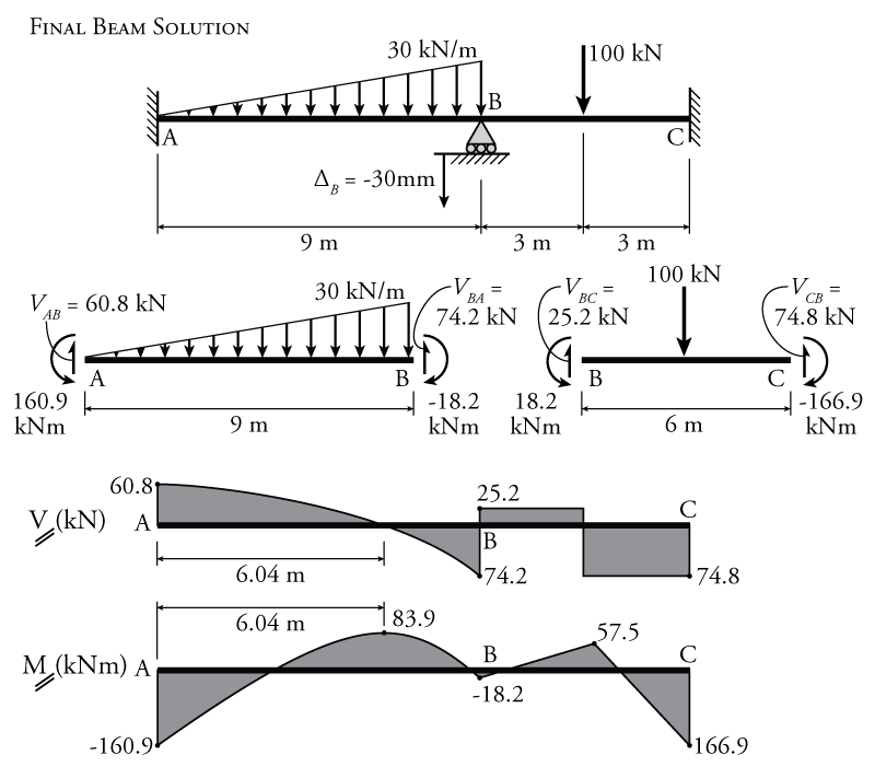
Using the known end shears, end moments and external loadings for each member, the shear and moment diagrams may be constructed easily as shown in Figure 9.11.