Learn About Structures
Let's start with a simple indeterminate system that is only ${1^\circ}$ indeterminate. Such a system is shown in Figure 8.1. This system is a beam with a pin support and two roller supports, giving it four reaction components, but only three equations of equilibrium. We cannot find the moment diagram for this beam using any of the methods that we have learned so far.
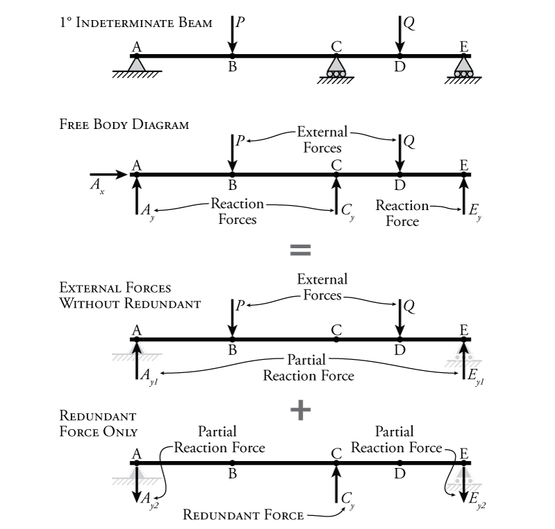
The way that we will deal with the beam in Figure 8.1 is to break the problem up into determinate parts (using superposition) and then reconcile those parts with each other using compatibility. Recall that, from the beam's point of view, there is no real difference between a load caused by an external force, and a load caused by a reaction force. The only difference between external forces and reaction forces is that we know that at the reaction force location, the deformation/rotation associated with that reaction component is zero. A reaction force component serves to keep the structure in place, either by restraining a displacement, or by restraining a rotation. This known displacement/rotation at the reaction component location gives us some additional information about how the structure behaves, beyond what we can tell about the structure from equilibrium alone. For example, in Figure 8.1 the top diagram shows the beam with the reactions boundary conditions shown, and the second diagram from the top shows the free body diagram for that beam subjected to the given external forces (with reaction boundary conditions replaced by the resulting reaction force components). The top diagram gives us additional information that the second diagram (the free body diagram) doesn't: it shows that the beam is restrained from moving vertically at point A, C, and E. This is information about the compatibility of the beam. This extra compatibility information is not required when we are analysing the shears and moments in a determinate beam; however, when we are analysing an indeterminate beam, we can put it to use.
To take advantage of this extra compatibility information at the reaction supports, we will divide our free body diagram in Figure 8.1 into two separate systems using superposition. To start with, we will choose one of the reaction components to be our redundant force. We will treat this reaction component in a special way, by considering what would happen if the support reaction itself wasn't there, but the force component of the reaction was (i.e. the beam is not restrained from displacing at that point). For the system shown in Figure 8.1 , the roller reaction at point C has been chosen as the redundant force. So, we remove the support, but keep the equivalent reaction force $C_y$, which we will now call our redundant force (although we don't know the value of $C_y$ yet). This means that in our analyses, the beam will be allowed to displace at point C. The support reactions at points A and E will remain as they were. For this beam, by removing the support reaction at C and then treating the equivalent reaction force as an external force, we have changed our ${1^\circ}$ indeterminate system into a determinate system. This new determinate system, without the reaction support associated with the redundant force is called the primary system. Later, we will bring the compatibility at C back into play (i.e. the fact that there is actually a reaction support there and the vertical displacement is zero).
Without the support at C, and treating the reaction force $C_y$ as if it was an external force, we can divide the full behaviour of the beam into two different systems using superposition as shown in Figure 8.1. One system will have the real external forces $P$ and $Q$ ('external forces without redundant' in the figure), and the other system will have only the redundant force $C_y$ ('redundant force only' in the figure). Both of these systems will be allowed to deflect at point C, but not at points A and E (the supports at A and E are still considered to exist). For each system, the forces will cause reaction forces at A and E, and some vertical deflection at point C. If the force at point C ($C_y$) is correct, then the superposition of these two systems will give us back the full free body diagram for the beam, and the sum of the reaction forces for the two systems will give us the total reaction forces for the full beam system.
Why are we doing all of this? Because now we can use the superposition of the deformations of the two separate systems to find the redundant force ($C_y$) which is our true reaction force at point C in the system. Recall from the previous discussion on superposition (see Chapter 5) that superposition applies to both forces/moments and deformations of a structure. So, the deformation of the system with only the external forces (without the redundant force) summed with the deformation of the system with only the redundant force will equal the full deformation of the real full beam. This is illustrated in Figure 8.2.
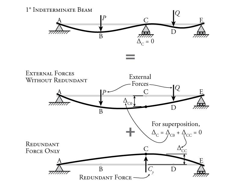
The top diagram in Figure 8.2 shows the deformation of the full indeterminate beam with the reaction at point C still in place. Of course, we know that the vertical deformation at point C ($\Delta_C$) must be equal to zero, as shown. Once we eliminate the support at C, giving us our primary system, we can apply the two components of the superimposed system and measure the deflection at point C for each. For the first one, we only apply the external reactions $P$ and $Q$ to the primary system. Since the primary system is determinate, we can easily find the vertical displacement at point C ($\Delta_{C0}$) using one of the methods from Chapter 5, assuming that we are given the magnitudes of the forces $P$ and $Q$. For the second of the superimposed systems, only the redundant force $C_y$ is applied to the primary system with the goal of determining the vertical displacement that the redundant force causes at point C ($\Delta_{CC}$). Of course, unlike for $P$ and $Q$, we don't actually know the value of the redundant force since that is what we are trying to find.
Superposition and compatibility together give us one extra piece of information. The two superimposed displacements at point C ($\Delta_{C0}$ and $\Delta_{CC}$) must add together to get the total displacement at point C ($\Delta_C$) in the real beam, which we know must be equal to zero since there is actually a vertical support at that location. This means that:
\begin{equation} \boxed{ \Delta_C = \Delta_{C0} + \Delta_{CC} = 0 } \label{eq:compat-cond-1} \tag{1} \end{equation}
This equation may be called our compatibility condition for this problem.
We can't directly use this compatibility condition to solve for $C_y$ because we don't have a readily available method for calculating the force in a structure that is required to achieve a known deflection (all of the methods from Chapter 5 find the deflection caused by a given force). But, we can find how much deflection at C (part of $\Delta_{CC}$) would be caused by each unit or each $1\mathrm{\,kN}$ piece of the force $C_y$. We find this by applying a unit load at point C in the same direction as the redundant force $C_y$, and then finding the deflection at C caused by that unit force. This gives us the amount of deflection at C caused by each $\mathrm{kN}$ of $C_y$ and is called the flexibility coefficient ($f_{CC}$). This flexibility coefficient has units of length divided by force (e.g. $\mathrm{mm/kN}$). So, the total deflection caused by redundant force $C_y$ is equal to:
\begin{equation} \Delta_{CC} = f_{CC} C_y \label{eq:flex-coeff} \tag{2} \end{equation}
where $\Delta_{CC}$ is the total deflection of the primary system at point C caused by the redundant force $C_y$, and $f_{CC}$ is the deflection of the primary system at point C caused by a single unit load ($1\mathrm{\,kN}$) at point C. If we sub equation \eqref{eq:flex-coeff} into equation \eqref{eq:compat-cond-1}, then we get:
\begin{equation} \boxed{ \Delta_{C0} + f_{CC} C_y = 0 } \tag{3} \end{equation}
and, then we can rearrange to solve for the redundant force $C_y$:
\begin{equation} \boxed{ C_y = \frac{-\Delta_{C0}}{f_{CC}} } \tag{4} \end{equation}
This solution for $C_y$ gives us the exact amount of force necessary at point C to keep point C in place vertically (when the system is subjected to forces $P$ and $Q$). So, since $C_y$ is the exact right amount of force needed to keep the displacement at C equal to zero, it doesn't actually matter that we removed the support at C when we started treating the reaction at C as a redundant force instead of a reaction force. The amount that the beam is pushed downwards at point C by the external forces $P$ and $Q$ is exactly balanced by the amount that the beam is pushed upwards at point C by the redundant force $C_y$.
Once we have solved for the reaction force at C ($C_y$), we have only three unknown reaction forces left: $A_x$, $A_y$, and $E_y$ (assuming $P$ and $Q$ are known). So, it is a trivial exercise now to use the three equilibrium equations to solve for these unknowns. From there, once we know all of the reactions, we can draw the shear and moment diagrams.
The choice of $C_y$ as our redundant reaction was somewhat arbitrary. We could also have chosen $A_y$ or $E_y$ as the redundant force instead; however, $C_y$ is a bit easier because when the support at C is removed, we are left with a primary system that is a simply supported beam, which is easy to analyse for deflections. We could not have chosen $A_x$ as a redundant force because the removal of the reaction component $A_x$ would make the resulting primary system unstable, which means that it would be impossible to analyse to determine deflections.
It is also important to note that for a structure with a fixed support, a moment reaction could be chosen to be the redundant force. In this case, the compatibility condition would relate the rotations at the redundant location instead of the deformations, for example:
\begin{align*} \theta_C = \theta_{C0} + \theta_{CC} = 0 \end{align*}
and the flexibility coefficient would relate a unit moment to the rotation caused by that moment (units of $\mathrm{1/{kNm}}$):
\begin{equation} \boxed{ \theta_{CC} = -f_{CC} M_C } \label{eq:Moment-Compat} \tag{5} \end{equation}
This same method is also directly applicable to indeterminate frames and trusses, as we will see.
Example
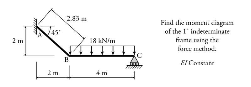
The force method with an external reaction redundant force will be illustrated using the example frame structure shown in Figure 8.3. This simple frame is ${1^\circ}$ indeterminate and has a constant $EI$ for all members.
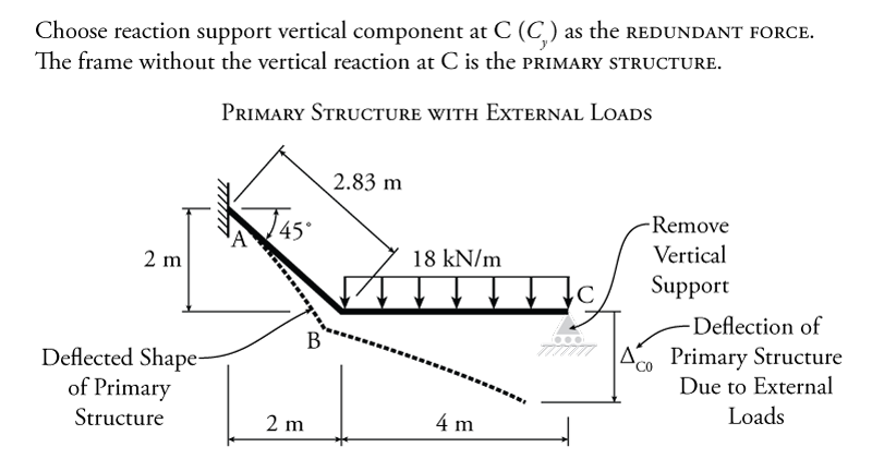
The first step is to select which reaction component to use as the redundant force. In this case, the easiest one would be the vertical reaction at point C ($C_y$). This is because, once the reaction at C is removed, the primary system is effectively a cantilever, which is very easy to analyse. Of course $A_y$ and $M_A$ would also work as redundants (but not $C_x$, because removing it would make the primary system unstable). The resulting primary structure is shown in Figure 8.4.
With $C_y$ selected as the redundant force, the compatibility condition for this problem is:
\begin{align*} \Delta_{C0} + \Delta_{CC} = 0 \end{align*}
where $\Delta_{C0}$ is the deflection of the primary system at point C due to the external loads only, $\Delta_{CC}$ is the deflection of the primary system at C due to the redundant force only, and 0 is the necessary result of the superposition of the two deflections. The two deflections must add to zero because in the full indeterminate structure there is a vertical support at C which restrains the structure's vertical deflection at that location.
As with the beam discussed previously, the first step to finding the redundant force is to find $\Delta_{C0}$, the deflection of the primary structure (primary system) due to the external loads only (without the redundant force). This structure and the corresponding deflected shape are shown in Figure 8.4. Since this structure is a frame, we cannot use the moment area method or the conjugate beam method to solve for the deflection $\Delta_{C0}$, we must use the virtual work method.
The virtual work analysis of the primary structure with the external load is shown in Figure 8.5. For this virtual work analysis, the real system is the primary structure with the external load (as shown), and the virtual system is the primary structure with a single vertical unit load at point C (since we are trying to find the vertical deflection of the real system at point C). The resulting real shear diagram and real curvature diagram for the real system are shown in the figure right below the real system. The moment diagram would have the same shape as the curvature diagram for this system (not shown), since $EI$ is constant for all of the members. The virtual shear diagram and virtual moment diagram for the virtual system are also shown.
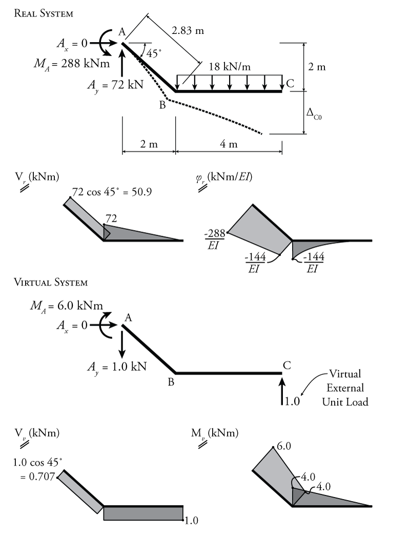
+Using the virtual work methods from Chapter 5 (and using the Product Integration table in Figure 5.22) we can find the vertical deflection at C:
\begin{align*} W_{v,i} &= \frac{LMQ}{4} + \frac{L}{6} \left[ Q_a (2M_a + M_b) + Q_b (M_a + 2M_b) \right] \\ W_{v,i} &= - \frac{576\mathrm{\,kN^2 m^3}}{EI} - \frac{3124\mathrm{\,kN^2 m^3}}{EI} \\ W_{v,i} &= \frac{-3700\mathrm{\,kN^2 m^3}}{EI} \end{align*}
Applying the virtual work balance:
\begin{align*} W_{v,e} &= W_{v,i} \\ (\Delta_{C0} )(1\mathrm{\,kN}) &= \frac{-3700\mathrm{\,kN^2 m^3}}{EI} \\ \Delta_{C0} &= \frac{-3700\mathrm{\,kN m^3}}{EI} \end{align*}
Now we have found $\Delta_{C0}$ which is one part of our compatibility condition. Next, we need to find the effect of a unit redundant on the deflection of the primary system at point C (without the external loads). We will also use virtual work for this as shown in Figure 8.6.
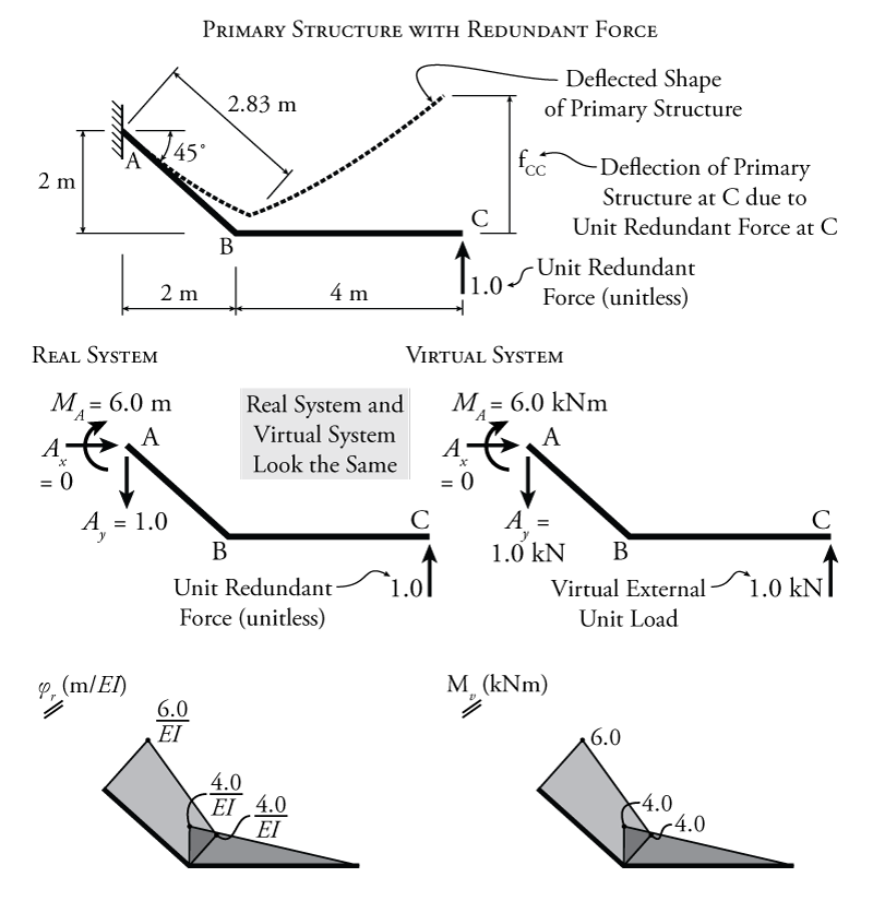
For the virtual work analysis shown in Figure 8.6, the real system is the primary structure with a unit redundant force at point C as shown in the figure. It is important to note that the unit redundant force is not applied as $1\mathrm{\,kN}$ like a virtual load, it is unitless (or in units of $\mathrm{kN/kN}$) because we want to find the values per kN of applied redundant force. To find the deflection at C due to that unit redundant force, we need to create a virtual system with a virtual external unit load at point C (in the same direction as the redundant). This means that the real and virtual systems for finding the effect of a unit redundant force are functionally identical as shown in the figure. These real and virtual systems, which are identical to each other, also happen to be identical to the virtual system from Figure 8.5 (which was being used to find the deflection of the primary system caused by the external loads on the system without the redundant). So, both the real and virtual system results for the unit redundant analysis in Figure 8.6 may be taken directly from the previous virtual system from Figure 8.5. This saves some analysis work since the moment diagrams will be the same for all three. The only difference may be that the curvature diagram for the real system in Figure 8.6 may be a bit different if $EI$ were not constant. The proper units for the real system are also a bit different for the unit redundant analysis because the unit redundant does not have a units (i.e. it is in units of $\mathrm{kN/kN}$ as mentioned previously).
Using the virtual work method with these real and virtual systems, we can solve for the flexibility coefficient $f_{CC}$ which is the deflection of the primary structure at C due to a unit redundant force at C (as shown in the top diagram in Figure 8.6):
\begin{align*} W_{v,i} &= \frac{LMQ}{3} + \frac{L}{6} \left[ Q_a (2M_a + M_b) + Q_b (M_a + 2M_b) \right] \\ W_{v,i} &= \frac{21.3\mathrm{\,kN^2 m^3}}{EI} + \frac{71.7\mathrm{\,kN^2 m^3}}{EI} \\ W_{v,i} &= \frac{93.0\mathrm{\,kN m^3}}{EI} \end{align*}
Applying the virtual work balance:
\begin{align*} W_{v,e} &= W_{v,i} \\ (f_{CC} )(1\mathrm{\,kN}) &= \frac{93.0\mathrm{\,kN m^3}}{EI} \\ f_{CC} &= \frac{93.0\mathrm{\,m^3}}{EI} \end{align*}
Now that we have the flexibility coefficient we can revisit our compatibility condition to solve for the magnitude of the redundant force:
\begin{align*} \Delta_{C0} + \Delta_{CC} &= 0 \\ \text{but} \; \Delta_{CC} &= f_{CC} (C_y) \\ \therefore \; C_y &= \frac{-\Delta_{C0}}{f_{CC}} \\ C_y &= - \left( \frac{-3700\mathrm{\,kN m^3}}{EI} \right) \left( \frac{EI}{93.0\mathrm{\,m^3}} \right) \\ C_y &= +39.8\mathrm{\,kN} \\ C_y &= 39.8\mathrm{\,kN} \uparrow \end{align*}
Since we assumed that the unit redundant force pointed upwards in our analysis (as shown in Figure 8.6), a positive result for $C_y$ confirms that the reaction actually points upwards.
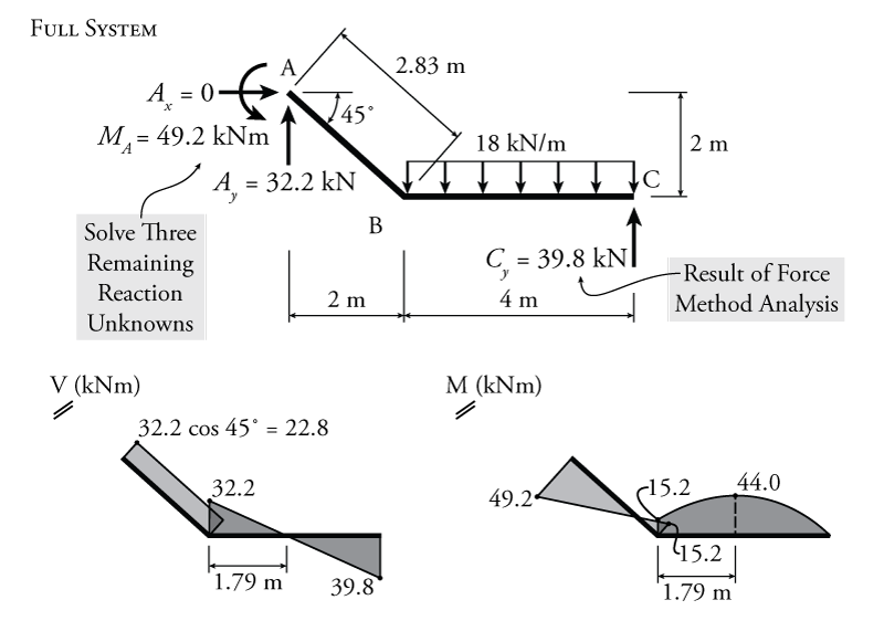
After all of this analysis, we have managed to determine the magnitude of the reaction component $C_y$. Knowing this, there are only three unknown reactions remaining in the indeterminate system as shown in Figure 8.7, $A_x$, $A_y$, and $M_A$. These may now be easily found using equilibrium and their values are shown in Figure 8.7. Once the reactions are all known the shear and moment diagrams may be drawn as shown in the figure.