 Learn About Structures
If a structure is externally determinate, then all of the reactions may be calculated using equilibrium alone. To determine whether a structure is externally determinate, the following equations are used:
\begin{align} \tag{1} \text{Statically unstable externally: } r < 3 + e_c \label{eq:SE-Unstable} \\ \tag{2} \text{Statically determinate externally: } r = 3 + e_c \label{eq:SE-Det} \\ \tag{3} \text{Statically indeterminate externally: } r > 3 + e_c \label{eq:SE-Indet} \end{align}
where $r$ is the number of reaction components, and $e_c$ is the number of equations of condition. Both of these are described in detail below.
The degree of indeterminacy $i_e$ is given by the following equation, which is based on equation \eqref{eq:SE-Indet} above:
\begin{equation} \tag{4} \boxed{i_e = r - (3 + e_c)} \label{eq:SE-DegreeIndet} \end{equation}
If this equation results in $i_e = 0$, the structure is determinate; if it results in $i_e < 0$, then the structure is unstable. Otherwise, $i_e$ is the degree of indeterminacy (i.e. how many extra redundant forces there are).
Reaction Components
In the equations above, $r$ is equal to the total number of reaction components as shown in Table 2.1 for 2D systems. Different types of supports have a different number of reaction components based on the way that the support restrains the movement of the structure.
| Support Type | Schematic | Reactions | $r$ |
|---|---|---|---|
| Roller | 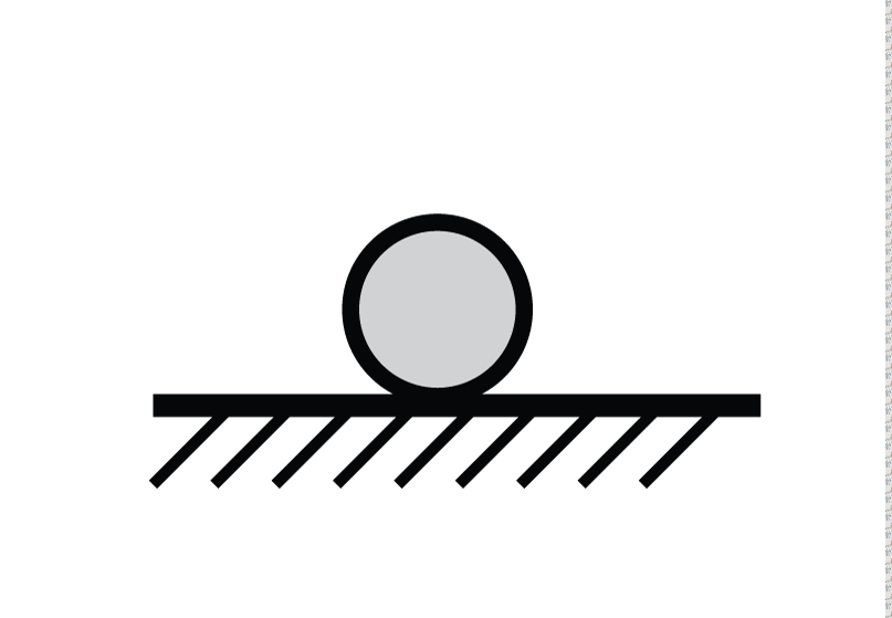 |
 |
$r=1$ |
| Pin |  |
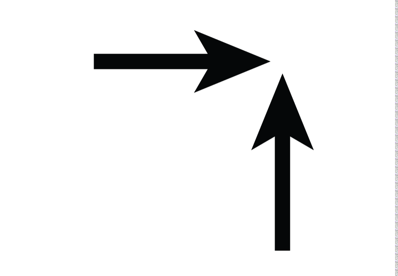 |
$r=2$ |
| Fixed | 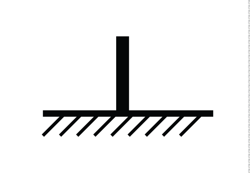 |
 |
$r=3$ |
For multiple reaction points, $r$ is the sum of all the components for all the reaction points in the structure.
Equations of Condition
The parameter $e_c$ is the number of equations of condition. These are release conditions within the structure that provide extra equilibrium equations beyond the three for global equilibrium. For example, if an internal hinge is added to the structure, as shown in Figure 2.2, then that hinge provides one equation of condition to the structure ($e_c = 1$) because there is a known internal moment at that location. If there was no internal hinge in this example, then the structure would be indeterminate and it would not be possible to find the reaction forces or the internal forces (since it has four reaction components). The addition of the hinge provides an additional equilibrium condition which forces the internal moment to be equal to 0 at point B ($\sum {M_B} = 0$). This can be demonstrated by splitting the structure into two free body diagrams as shown in the lower part of Figure 2.2. At point B, there are three internal force components that exist in equal and opposite action/reaction pairs on either side of point B:
- Axial Force: $B_x^{AB}$ and $B_x^{BC}$
- Shear Force: $B_y^{AB}$ and $B_y^{BC}$
- Moment: $M_B^{AB}$ and $M_B^{BC}$
So, $M_B^{AB} = M_B^{BC} = 0$, because they are action reaction pairs.
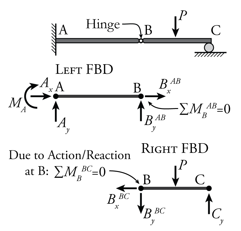
Therefore, one extra equilibrium equation is added to the system due to the introduction of the hinge: either $\sum {M_B^{AB}} = 0$ or $\sum {M_B^{BC}} = 0$. Only one of these equations counts because the two equations are not independent. They are not independent because they both mean the same thing, that the moment at the hinge is zero. If I know the moment on one side of the cut is zero, then I know automatically as well that the moment on the other side of the cut must be zero. So, for each internal hinge in a structure, there is a single equation of condition: $e_c = 1$.
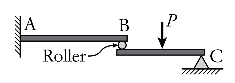
For a structure with an internal roller, such as that shown in Figure 2.3, both the force transfer in the direction of the roller and the moment are equal to zero at the location of the roller. This provides two extra equilibrium equations, and therefore two equations of condition. For the structure shown in Figure 2.3, the extra equations are:
\begin{align*} \sum {M_B^{AB}} &= 0 \text{ or } \sum {M_B^{BC}} = 0 \\ \text{and} \\ \sum {B_x^{AB}} &= 0 \text{ or } \sum {B_x^{BC}} = 0 \end{align*}
So, each internal roller adds two equations of condition to the problem: $e_c = 2$.
If there are more than two members that frame into a single internal hinge, then there is an additional equation of condition for each additional member. For example, for three members connected at a hinge, then there are two independent equilibrium equations that are added to the system. If I know that two members at the hinge have zero moment, then I know automatically that the third one must also be zero because the sum of moments at the hinge must be zero. Therefore only two of these moments are independent. So, for a hinge connection with multiple elements, $e_c = n - 1$ where $n$ is equal to the number of members connected to the hinge. Similarly, for a roller connection with multiple members, each additional member adds two equations of condition, $e_c = 2 * (n - 1).$
In summary:
\begin{align} \tag{5} \text{For a Hinge: }e_c &= n - 1 \label{eq:ec-hinge} \\ \tag{6} \text{For a Roller: }e_c &= 2 (n - 1) \end{align}
where $n$ is the number of members connected to the hinge or roller. For multiple hinges and rollers, the total $e_c$ is the sum of the $e_c$ values from each pin or roller.