- What are the assumptions of the Bernoulli-Euler beam theorem?
- Determine the slope $\theta(x)$ and deflection $\Delta(x)$ equations for the beam below using the direct integration method. Assume $EI$ is constant.
- Determine the slope $\theta(x)$ and deflection $\Delta(x)$ equations for the beam below using the direct integration method. Assume $EI$ is constant.
- For the beam shown below, determine the slope at midspan ($\theta_{mid}$), slope at point B ($\theta_B$), deflection at midspan ($\Delta_{mid}$) and deflection at point B ($\Delta_B$) using the moment area theorems.
- For the beam shown below, determine the slope to the left of the hinge at point B ($\theta_{B,left}$), slope to the right of the hinge at point B ($\theta_{B,right}$), deflection at point B ($\Delta_{B}$) and deflection at point D ($\Delta_D$) using the moment area theorems.
- For the beam shown below, determine the location and value of the maximum deflection using the moment area theorems. You must find and compare all potential local maxima and minima.
- For the beam shown below, determine the location and value of the maximum deflection using the moment area theorems. You must find and compare all potential local maxima and minima.
- Repeat problem 5 using the conjugate beam method.
- For the beam shown below, determine the slope and deflection at Point B ($\theta_B$, $\Delta_B$) and at point D ($\theta_D$, $\Delta_D$) using the conjugate beam method.
- For the beam shown below, determine the slope and deflection at Point B ($\theta_B$, $\Delta_B$) and at point C ($\theta_C$, $\Delta_C$) using the conjugate beam method.
- For the beam shown below, determine the minimum moment of inertia ($I$) such that its deflection does not exceed $\frac{L}{360}$.
- For the beam shown below, determine the minimum moment of inertia ($I$) such that its deflection does not exceed $\frac{L}{360}$. Use the length of each span (AB and BC) to calculate the maximum deflection for each.
- For the beam shown below, determine the deflection at point C ($\Delta_C$) using the virtual work method.
- For the beam shown below, determine the rotation at point A ($\theta_A$) and the deflection at point D ($\Delta_D$) using the virtual work method.
- For the beam shown below, use virtual work to determine the minimum moment of inertia ($I$) such that its deflection does not exceed $\frac{L}{360}$.
- For the beam shown below, use virtual work to determine the minimum moment of inertia ($I$) such that its deflection does not exceed $\frac{L}{360}$.
- For the frame shown below, determine the vertical deflection at point C ($\Delta_C$) using the virtual work method.
- For the frame shown below, determine the rotation and vertical deflection at point A ($\theta_A$, $\Delta_A$) using the virtual work method.
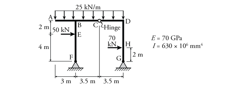
- For the frame shown below, determine the rotation at point D ($\theta_D$) and the horizontal deflection at point E ($\Delta_E$) using the virtual work method.
- For the truss shown below, determine the vertical deflection at point B ($\Delta_B$) and the horizontal deflection at point H ($\Delta_H$) using the virtual work method.
- For the truss shown below, determine the vertical deflection at point C ($\Delta_C$) and the vertical deflection at point F ($\Delta_F$) using the virtual work method.
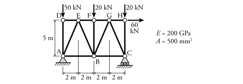
- For the truss shown below, use virtual work to determine the minimum cross-sectional area ($A$) such that the horizontal deflection at point H ($\Delta_H$) does not exceed $20\mathrm{\,mm}$.
- For the truss shown below, use virtual work to determine the minimum cross-sectional area ($A$) such that the vertical deflection at point C ($\Delta_C$) does not exceed $35\mathrm{\,mm}$.
- For the truss from problem 20 but with no external loads, determine the horizontal deflection at point F ($\Delta_F$) if members AE, AB, BC and CG experience a temperature increase of $50\mathrm{\,^\circ C}$ and member BF experiences a temperature decrease of $20\mathrm{\,^\circ C}$ ($\Delta T = -20\mathrm{\,^\circ C}$). Assume that $\alpha=1.2\times 10^{-5}\mathrm{\,/ ^\circ C}$.
- For the truss from problem 21 but with no external loads, determine the vertical deflection at point B ($\Delta_B$) if members BD, DF and AD were each fabricated $10\mathrm{\,mm}$ too short and member DE was fabricated $5\mathrm{\,mm}$ too long.
Resources for Structural Engineers and Engineering Students
 Learn About Structures


