 Learn About Structures
For analysis of frame deflections using virtual work, the process is exactly the same as for beams, as long as we can still assume that the deformations due to axial forces and shear are still insignificant relative to the bending deformations. This is still usually a good assumption for frames. One example of when this may not be a good assumption is for a tall frame structure, where the axial deformation of the columns on either side of the frame may contribute significantly to the lateral displacement at the top of the building. This type of frame effectively acts as a cantilever, with bending tension and compression stresses being taken by columns on either side of the building. Another situation when this may not be a good assumption is for short deep beams in bending and shear, where the shear deformations may become significant relative to the bending deformations.
To consider axial deformations in addition to bending (which is typically not necessary for frames), an additional term is simply included in the total internal virtual work:
\begin{equation} \boxed{W_{v,i} = \int_0^L \frac{M_vM_r}{EI} dx + \sum_j \left( \frac{p_{rj} L_j}{E_j A_j} \right) p_{v_j} } \label{eq:Virtual-Work-Internal-Frames} \tag{1} \end{equation}
where $p_{rj}$ is the real internal axial force in member $j$ (as long as the axial force is constant), $L_j$ is the length of member $j$, $E_j$ is the Young's modulus of member $j$, $A_j$ is the cross-sectional area of member $j$, and $p_{v_j}$ is the virtual internal axial force in member $j$. The second term in this equation is the same expression for internal virtual work that is used for truss members as described previously.
If axial force is not considered, then the equation for the internal virtual work for beams (equation \eqref{eq:Virtual-Work-Internal-Beams}) may be used:
\begin{equation} \boxed{W_{v,i} = \int_0^L \frac{M_vM_r}{EI} dx} \label{eq:Virtual-Work-Internal-Beams} \tag{2} \end{equation}
For frames with multiple members, the total internal virtual work is simply the sum of the internal virtual work for each member.
Example
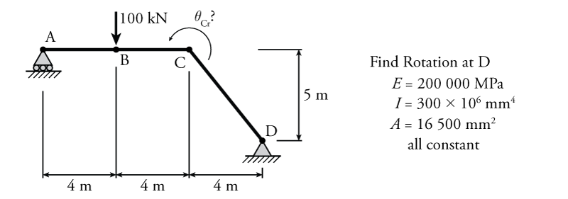
The use of virtual work to find the rotation of a single point in a frame will be illustrated using the example frame shown in Figure 5.25. Work arising from both bending and axial deformations will be considered to the consequence (or lack of consequence) associated with neglecting the axial work. The frame has a constant $EI$ and cross-sectional area $A$ for all members. We would like to determine the rotation of joint C ($\theta_{Cr}$) due to the applied real external load at point B.
The real and virtual systems for this structure are analysed in Figure 5.26. The top of the figure shows the free body diagram for each system. The virtual external force on the virtual system for this problem is a unit point moment of $1\mathrm{\,kNm}$ at point C (because we want to find the rotation of point C). This point moment is assumed to be counter-clockwise, but if the resulting solution for $\theta_{Cr}$ is negative, then we will know that the rotation is actually clockwise. Below the free body diagrams, each system, real and virtual, is analysed to determine the axial load for each, the curvature diagram for the real system (the real internal deformation), and the moment diagram for the virtual system (the virtual internal force).
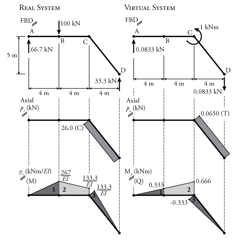
Since the axial force in member CD is constant for both the real and virtual systems, the internal virtual work contribution due to the axial forces may be easily determined using the second term of equation \eqref{eq:Virtual-Work-Internal-Frames}:
\begin{align*} W_{v,i, axial} &= \sum_j \left( \frac{p_{rj} L_j}{E_j A_j} \right) p_{v_j} \\ &= \frac{-26\mathrm{\,kN} (6.40\mathrm{\,m})}{ 200000\mathrm{\,MPa} (16500\mathrm{\,mm^2}) } (0.0650\mathrm{\,kN}) \\ &= \frac{-26000\mathrm{\,N} (6400\mathrm{\,mm})}{ 200000\mathrm{\,MPa} (16500\mathrm{\,mm^2}) } (65\mathrm{\,N}) \\ W_{v,i, axial} &= -3.28\mathrm{\,Nmm} = -3.28\times 10^{-6}\mathrm{\,kNm} \end{align*}
Notice that the real internal axial force was negative since it is a compression force and the virtual internal axial force was positive because it is a tension force.
Now, let's find the internal virtual work due to bending deformations using the expressions from Figure 5.22 to calculate the product integrals:
\begin{align*} W_{v,i, bending} &= \int \text{Section 1} + \int \text{Section 2} + \int \text{Section 3} \\ &= \frac{LMQ}{3} + \frac{L}{6} \left[ Q_a (2M_a + M_b) + Q_b (M_a + 2M_b) \right] + \frac{LMQ}{3} \\ &= \frac{1}{3} \left( 4 \right) \left( \frac{266.7}{EI} \right) \left( 0.333 \right) \\ & \;\; + \frac{4}{6} \left[ 0.333 \left( 2 \left( \frac{266.7}{EI} \right) + \frac{133.3}{EI} \right) + 0.666 \left( \frac{266.7}{EI} + 2 \left( \frac{133.3}{EI} \right) \right) \right] \\ & \;\; + \frac{1}{3} \left( 6.4 \right) \left( \frac{133.3}{EI} \right) \left( -0.333 \right) \\ &= \frac{118.4 + 384.8 - 94.7}{EI} \\ W_{v,i, bending} &= \frac{408.5\mathrm{\,kN^2m^3}}{EI} \\ W_{v,i, bending} &= \frac{408.5\times 10^15\mathrm{\,N^2mm^3}}{(200000\mathrm{\,MPa}) (300 \times 10^6\mathrm{\,mm^4})} \\ W_{v,i, bending} &= 6808.3\mathrm{\,Nmm} = 6810\times 10^{-6}\mathrm{\,kNm} \end{align*}
+So, $W_{v,i, axial}$ is approximately $0.05\%$ of $W_{v,i, bending}$ for this example problem. Therefore, it would clearly have been a reasonable assumption to neglect it. The accuracy of our numbers is about $0.1\%$ at best, recall the discussion of significant figures in Section 1.7.
So, continuing the problem without the contribution of the axial deformations to the total internal virtual work:
\begin{align*} W_{v,i} = W_{v,i, bending} \end{align*}
Applying the virtual work balance:
\begin{align*} W_{v,e} &= W_{v,i} \\ (1\mathrm{\,kNm}) (\theta_{Cr}) &= 6810\times 10^{-6}\mathrm{\,kNm} \\ \theta_{Cr} &= 0.00681\mathrm{\,rad} \end{align*} \begin{equation*} \boxed{\theta_{Cr} = {0.390^\circ} \curvearrowleft} \end{equation*}
The rotation is counter-clockwise because we assumed a counter-clockwise unit point moment and the result was positive.