 Learn About Structures
The use of virtual work for truss deflection analysis follows directly from the development of virtual work that was discussed in Section 5.6.
The real system will consist of the truss with all the real applied external loads. For that system, we will define an unknown deflection of a specific joint in a specific direction (this is the deflection that we want to find). This is our real external deformation. From the real system, we must also calculate all internal deformations of the truss elements. We can find these by first finding the forces in the truss elements (using method of joints) and then applying mechanics to calculate all the axial deformations of each.
The virtual system will of course be the same as the real system but without the real loads. It will only have a single external unit load (the virtual external force) which will be placed on the joint that we want to find the deflection for. This force must also be in the same direction as the deflection that we want to find. This virtual external force will create known virtual internal forces which may be found using an analysis of the truss (with the virtual external force only).
Together, these will result in the following virtual work balance for trusses:
\begin{equation} W_{v,e} = W_{v,i} \tag{1} \end{equation} \begin{equation} \boxed{1(\Delta_r) = \sum_{j=1}^n \left( p_{vj} \delta_{rj} \right)} \tag{2} \end{equation}
where $1$ is the virtual external unit load, $\Delta_r$ is the external real deflection, $p_{vj}$ is the virtual internal axial force in each truss member in the virtual system, and $\delta_{rj}$ is the real internal deformation of each truss element in the real system.
The real internal deformation for each member can be caused by the applied loading, temperature changes, fabrication errors, or any other source of deformation. These are all treated the same way, as long as you are consistent about whether elongation is considered positive or contraction is considered positive. In this book, elongation deformations will be considered positive, which correspond to deformations caused by tension forces, increase in temperature, or members that have been fabricated to be longer than necessary.
For truss member deformations caused by axial force, the real internal deformation of an individual member is:
\begin{equation} \boxed{\delta_{rj} = \frac{p_{rj}L}{EA}} \label{eq:strain_def} \tag{3} \end{equation}
where $p_{rj}$ is the real internal force in that member, $L$ is the length of the bar, $E$ is the Young's Modulus of the bar material, and $A$ is the cross-sectional area of the bar.
For truss member deformations caused by changes in temperature, the real internal deformation of an individual member is:
\begin{equation} \boxed{\delta_{rj} = \alpha (\Delta T) L } \label{eq:temp_def} \tag{4} \end{equation}
+where $\alpha$ is the coefficient of thermal expansion for the material, $\Delta T$ is the change in temperature (positive is increase, and negative is decrease), and $L$ is the length of the member. The typical coefficients of thermal expansion $\alpha$ for steel and concrete are both somewhere around $12.0\times 10^{-6}\mathrm{\,/ ^{\circ}C}$.
For truss member deformations caused by fabrication errors (i.e. a truss element was manufactured to be too long or too short), the real internal deformation of an individual member is:
\begin{equation} \boxed{\delta_{rj} = \text{change in member length} } \tag{5} \end{equation}
So, if the member was fabricated to be $10\mathrm{\,mm}$ too short, then $\delta_{rj} = -10\mathrm{\,mm}$.
Since superposition still applies, even for the analysis of a single truss element within a truss, if there are two different effects that elongate or contract the member in the real system, then the total deformation $\delta_{rj}$ is the sum of the deformations from each effect. For example, if a truss member experiences both a tension force that would cause a $10\mathrm{\,mm}$ elongation and a decrease in temperature that would cause a $3\mathrm{\,mm}$ contraction, then the total real internal deformation of that member would be $\delta_{rj}=10-3=7\mathrm{\,mm}$.
Example
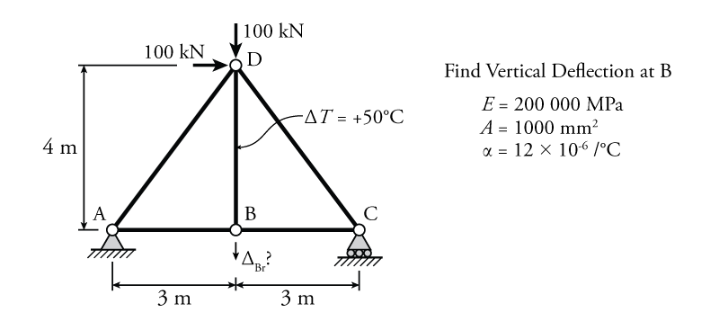
The use of the principle of virtual work to find deflections of trusses will be illustrated using the example truss structure shown in Figure 5.20. This is a simple determinate truss with two point loads at the top joint (joint D) and a temperature change on the member in the middle (member BD). The goal is to find the vertical deflection of point B.
The first step is to analyse the real structure to find all of the real internal truss deformations. To do this, we need the truss internal axial forces for all of the members. The result of this analysis is shown on the left side of Figure 5.21. This analysis is easily performed using the method of joints from Section 3.5. This analysis only finds the deformations in the truss members caused by the external forces on the truss, and does not include the deformation to member BD caused by the temperature change. That deformation will be considered later.
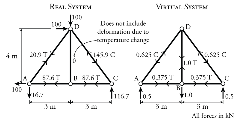
The next step is to construct an appropriate virtual system. Since we want to find the vertical displacement of joint B, we will add a virtual external unit force to joint B that acts vertically. This virtual system is shown on the right side of Figure 5.21. Notice that the unit load at B, while vertical, is pointing down. This means that we are assuming that the deflection of the real system at B ($\Delta_{Br}$) will be downwards. If, at the end of the solution, we get a negative value for $\Delta_{Br}$, this means that the assumption that we made about the direction was wrong and point B actually deflects upwards in the real system.
Once we have determined the location and direction of the virtual external unit load, we can analyse the truss using the method of joints to find the virtual internal axial forces in all of the members. The resulting internal forces are shown on the right side of Figure 5.21.
Looking at the virtual system in Figure 5.21, notice that we actually have more than one external virtual load, because there are reaction forces at joints A and C. The structure cannot tell the difference between external forces caused by loads and external forces caused by reactions. Will this cause problems for the virtual work analysis? Aren't we are only supposed to have one virtual external load? No, these reaction forces will not cause any problems, because they are applied at the support locations, where there are no displacements in either the real or virtual system (by definition). If there is no displacement at the location of an external force, then that force cannot do any work (and therefore will not be included in the virtual work balance).
We now have to calculate the deformations caused by the real internal forces and calculate the total internal virtual work (not forgetting about the real deformation caused by the temperature change on member BD, which we have not yet considered). This total internal virtual work is the sum of the internal virtual work done on each member in the truss. These calculations are summarized in Table 5.2.
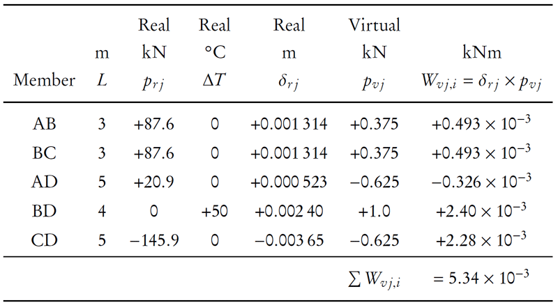
Table 5.2 has one row for each member in the truss. The column labelled $L$ is the row length. The column labelled $p_rj$ is the real internal force in each truss member $j$. These values come straight from the results of the analysis of the real structure in Figure 5.21 with positive values for tension force and negative for compression force. The next column labelled $\Delta T$ is the change in temperature for each member. The column labelled $\delta_{rj}$ is the real internal deformation of each truss member calculated as a sum of the deformation caused by the internal force and the deformation caused by the temperature change (a sum of equations \eqref{eq:strain_def} and \eqref{eq:temp_def}): \begin{equation*} \delta_{rj} = \frac{p_{rj}L}{EA} + \alpha (\Delta T) L \end{equation*} where \begin{align*} EA &= (200000\mathrm{\,MPa})(1000\mathrm{\,mm^2}) \\ &= 200000\times 10^3\mathrm{\,N} \\ &= 200000\mathrm{\,kN} \end{align*}
The next column labelled $p_{vj}$ is the virtual internal force in each truss member. These values come straight from the results of the analysis of the virtual structure in Figure 5.21 with positive values for tension force and negative for compression force. The last column labelled $W_{vj,i}$ is the internal virtual work for each truss member which is equal to the product of the internal virtual force and the internal real deformation. This column is summed at the bottom of the table to find the total internal virtual work in the truss system.
Now that we have the total internal virtual work, we can use the virtual work balance to calculate the real external deflection that we are trying to find:
\begin{align*} W_{v,e} &= W_{v,i} \\ (1.0\mathrm{\,kN})(\Delta_{Br}) &= 5.34\times 10^E{-3}\mathrm{\,kNm} \\ \Delta_{Br} &= 5.34\times 10^{-3}\mathrm{\,m} \end{align*} \begin{equation*} \boxed{\Delta_{Br} = 5.34\mathrm{\,mm} \downarrow} \end{equation*}
We know that the deflection is down because we assumed a downwards unit load when we defined the virtual system loading and the resulting $\Delta_{Br}$ from the virtual work came out positive (so our assumption was correct).